EasyManuals Logo

HCFA Q Series User Manual

HCFA Q Series
88 pages
To Next Page IconTo Next Page
To Previous Page IconTo Previous Page
Page #71 background imageLoading...
Page #71 background image
69
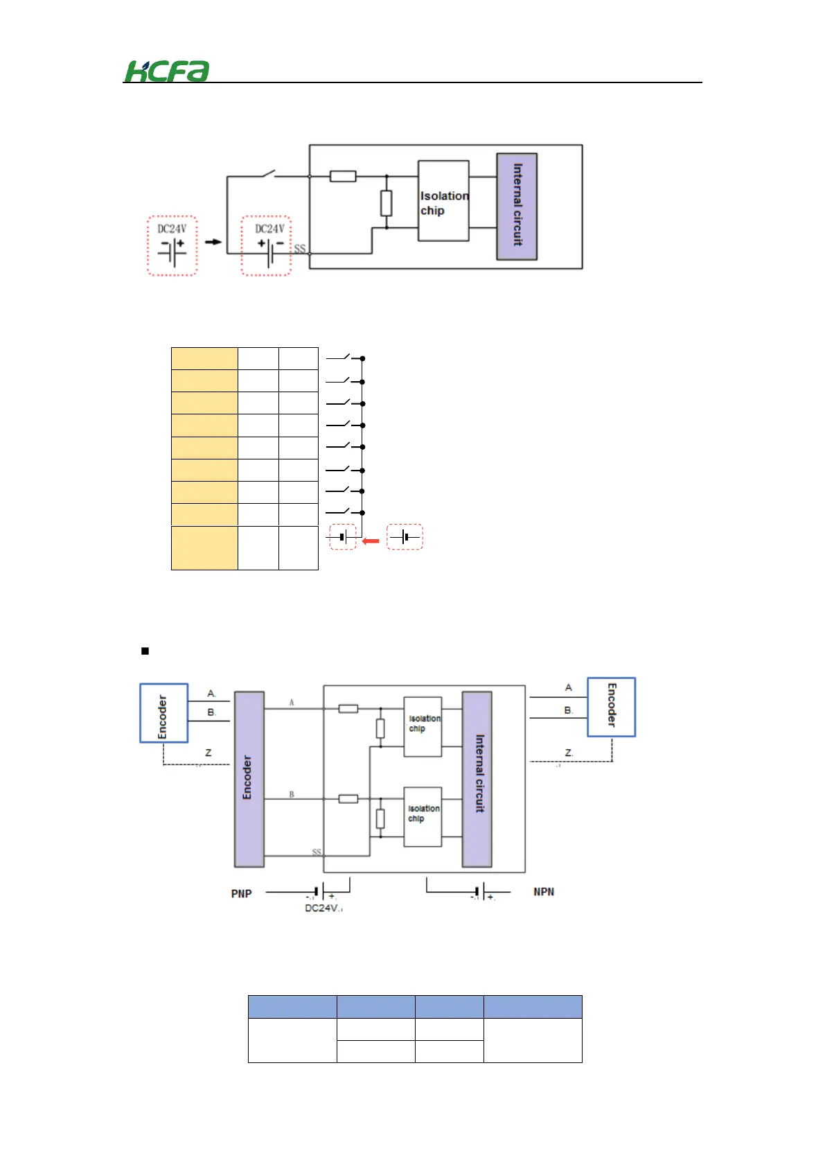
Internal/external circuit diagram of general inputs
Internal/external circuit diagram of high-speed inputs
HSInput
0
8
HSInput
1
9
HSInput
2
10
HSInput
3
11
HSInput
4
12
HSInput
5
13
HSInput
6
14
HSInput
7
15
Common
terminal
SS
SS
Channel
Port
Port
Channel
hsi_cnt
X0
X8
hsi_cnt4
X1
X9
*S/S is intermal short-circuit, other channels are not
connected, such the example of I8-I15.
Wiring diagram
+
+
-
-
DC24V
R0~R15
DC24V
PNP
Internal circuit
NPN
Internal circuit
*S/S is internal short-circuit
other channels are not connected
take the
single-channel as the example.

Table of Contents

Questions and Answers:

Question and Answer IconNeed help?

Do you have a question about the HCFA Q Series and is the answer not in the manual?

HCFA Q Series Specifications

General IconGeneral
BrandHCFA
ModelQ Series
CategoryController
LanguageEnglish