64
About the contact protection
When using clutches, motors, electromagnetic coils or other inductive load, surge current will occur at
power-on, and inverter voltage will occur at power-off. Surge current and inverter voltage drop
significantly shorten the life of short contacts. To suppress this, please set the contact protection circuit.
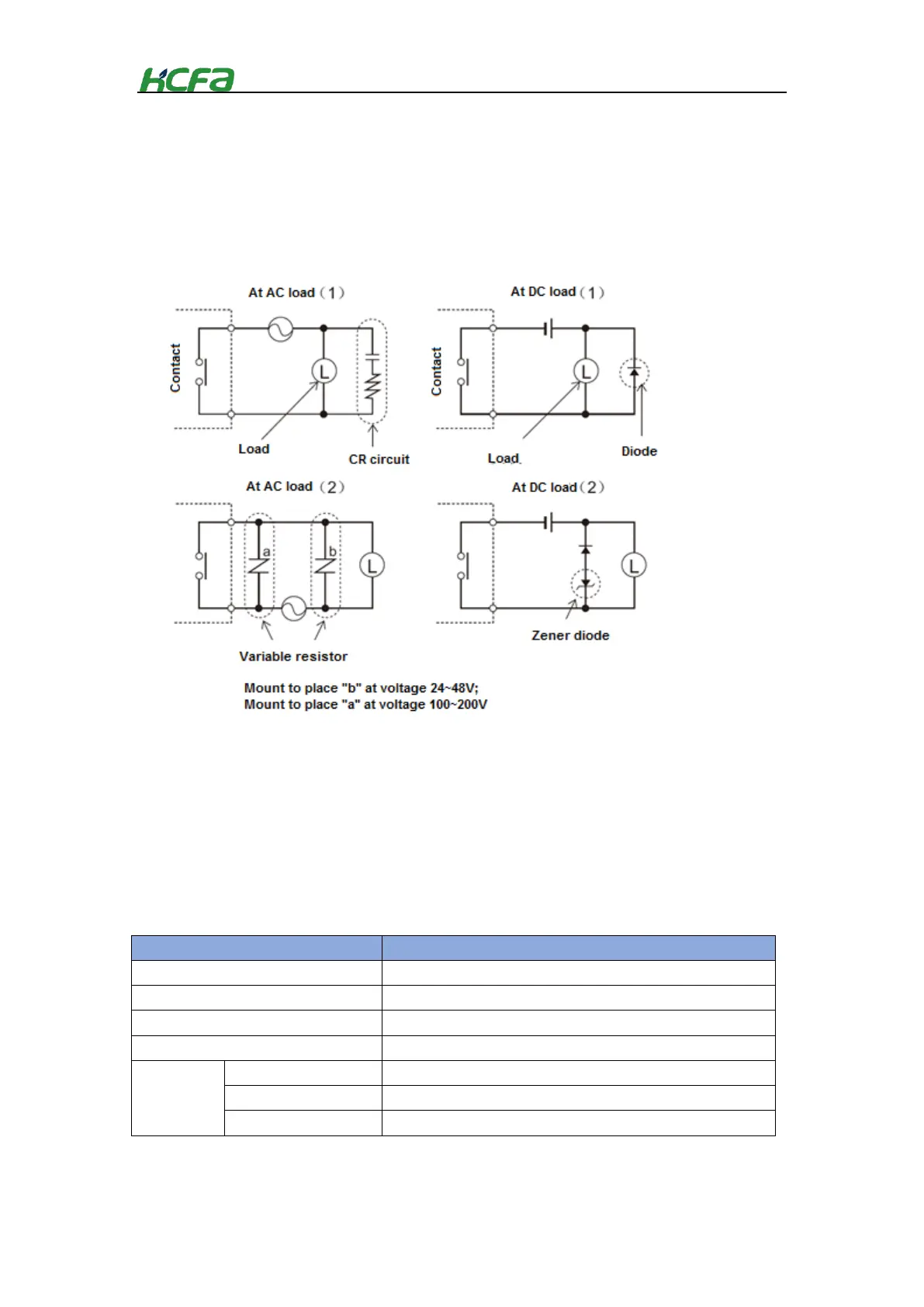
Contact protection circuit examples
The load coil rating should be less than the contact capacity.
The reverse withstand voltage of the diode should be 10 times greater than circuit voltage, and the
positive current should be greater than load current.
The diode, nonlinear resistor and CR circuit should be installed directly on the relay coil terminal.
4-2-3 Connector installation and wiring
Connector cable requirement
Pay attection to the following precautions before connector wirinfg:
Use the cables that meet the following requirements
Table 0-1Connector cable requirements
Pushing force (single contact)
Copper wire only (aluminum wire cannot be used)
After wiring, make sure that the connector contacts fully clamp the cable
 Loading...