EasyManuals Logo

HCFA Q Series User Manual

HCFA Q Series
88 pages
To Next Page IconTo Next Page
To Previous Page IconTo Previous Page
Page #73 background imageLoading...
Page #73 background image
71
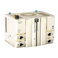
4-3-2 EC coupler wiring
As a remote extension coupler of Q series PLC, EC module provides 24V power supply for other
extension modules through its side metal sheet. Unlike other remote extension I/O modules, it’s not
necessary for EC module to use all the ports. The wiring diagram is shown as below:
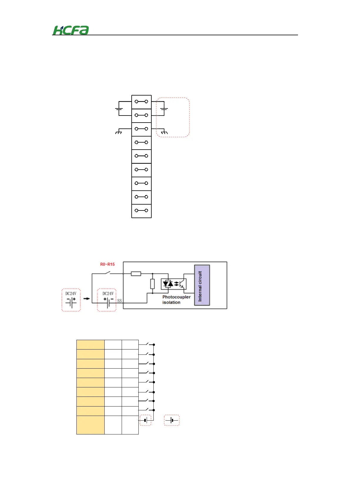
4-3-3 Digital input module wiring
As the remote extension module of Q-seires CPU unit, the module cannot work alone and needs to be
connected to the EC coupler or the right side of CPU unit. The wiring diagram is shown below:
DI
0
8
DI
1
9
DI
2
10
DI
3
11
DI
4
12
DI
5
13
DI
6
14
DI
7
15
Common
terminal
SS
SS
Wiring diagram
DC24V
DC24V
* The 2 channels of EC module
are internally connected, so just
connect 24VDC to one channel.
FG
FG
Wiring diagram
Internal circuit
+
+
-
-
DC24V
DC24V
PNP

Table of Contents

Questions and Answers:

Question and Answer IconNeed help?

Do you have a question about the HCFA Q Series and is the answer not in the manual?

HCFA Q Series Specifications

General IconGeneral
BrandHCFA
ModelQ Series
CategoryController
LanguageEnglish