EasyManuals Logo

HCFA Q Series User Manual

HCFA Q Series
88 pages
To Next Page IconTo Next Page
To Previous Page IconTo Previous Page
Page #16 background imageLoading...
Page #16 background image
14
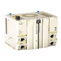
Table 0-3 Part names and function -2
Item
Name
Functions
(9)
Mounting hook
Install controller onto the DIN rail mounting hook
(10)
24VDC terminal block
24V DC power supply interface for CPU unit
(11)
Function keys
Used with dial switch
(12)
Dial switch
Used with function keys
(13)
RUN-STOP
Start or stop the CPU unit. Turn to the left to be off, turn to the right to be on
(14)
MINI USB
USB2.0 interface, will support the connection with PLC to monitor and download
user program
(15)
PORT1 EtherNet
Gigabit Ethernet support Modbus TCP
(16)
PORT2 EtherNet
Gigabit Ethernet support Modbus TCP
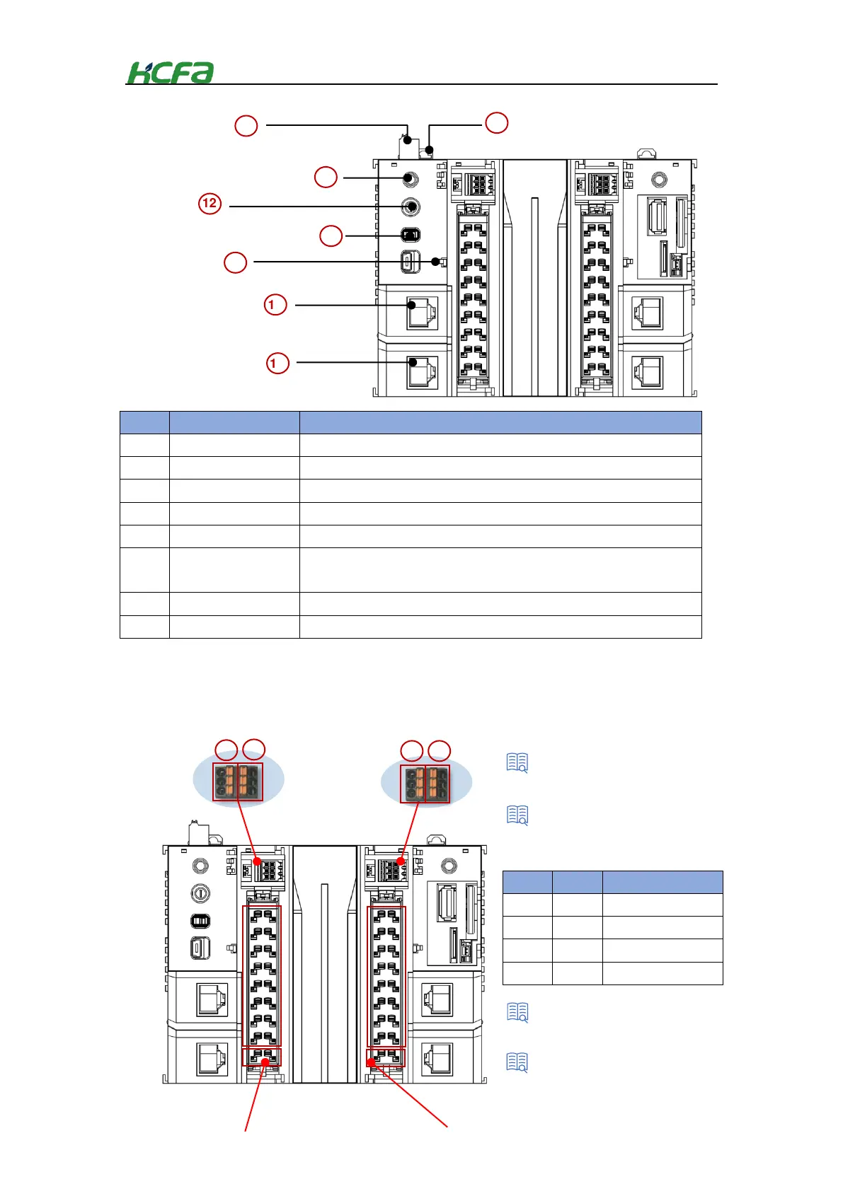
CPU unit high-speed I/O interface and communication interface
This unit is built-in high-speed I/O to realize the basic positioning function of single-axis. The frequency can reach up
to 200K.
Item
Name
Function
(17)
COM1
Support RS 485
(18)
COM2
Support RS 485
(19)
COM3
Support RS 232
(20)
CAN
Support CAN
9
10
Mounting hook
24VDC terminal
block
11
14
15
12
13
Function keys
Dial switch
RUN-STOP
16
MINI USB
PORT1 EtherNet
Support Modbus TCP
PORT2 EtherNet
,,
Support Modbus TCP
Serial indicator description
485/232/CAN spec.
COM1
COM3
CPU unit indicatordescription
“3-2-1 CP unit spec.
COM2
17
18
19
20
CAN
A1
B1
G
A2
B2
G
TX
RX
G
H
L
G
Table 0-4 Part names and function -3

Table of Contents

Questions and Answers:

Question and Answer IconNeed help?

Do you have a question about the HCFA Q Series and is the answer not in the manual?

HCFA Q Series Specifications

General IconGeneral
BrandHCFA
ModelQ Series
CategoryController
LanguageEnglish