32
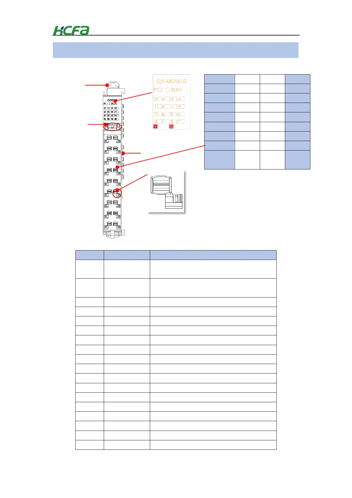
Table 0-15 Digital I/O module indicator description
The indicator show the current power supply status of the
module.
MD module running state. Lit means the module is in normal
running state
Input signal is detected by input channel 0.
Input signal is detected by input channel 1.
Input signal is detected by input channel 2.
Input signal is detected by input channel 3.
Input signal is detected by input channel 4.
Input signal is detected by input channel 5.
Input signal is detected by input channel 6.
Input signal is detected by input channel 7.
Output signal is detected by output channel 0.
Output signal is detected by output channel 1.
Output signal is detected by output channel 2.
Output signal is detected by output channel 3.
Output signal is detected by output channel 4.
Output signal is detected by output channel 5.
Output signal is detected by output channel 6.
Output signal is detected by output channel 7.
Part names for digital I/O module
terminal
* COM for input and output should be independent
from each other. Do not connect together internally.
 Loading...