59
Relationship between the value in 0x7010 and the output voltage
0x7010:0n(N=1、2、3、4): Setting value of corresponding output channel
After selecting the required working mode for DA modules in channel [0x80n0:01:=TRUE], the
setting value can be converted to
Value:Analog output value set by users
:Max. output range, refer to Table 3.1.10
:Mini. Output range, refer to Table 3.1.10
:Max. voltage of output range
:Mini. Voltage of output range
:Output voltage value
User display
The user display configuration is determined by index 0x80n0:01, where the user can modify the working
mode of the channel to display values in different measurement ranges
The analog module has a 16-bit resolution and the maximum display range is -〖32768〗_dec to +〖32767〗
_dec. The measured and displayed values in different modes are as follows:
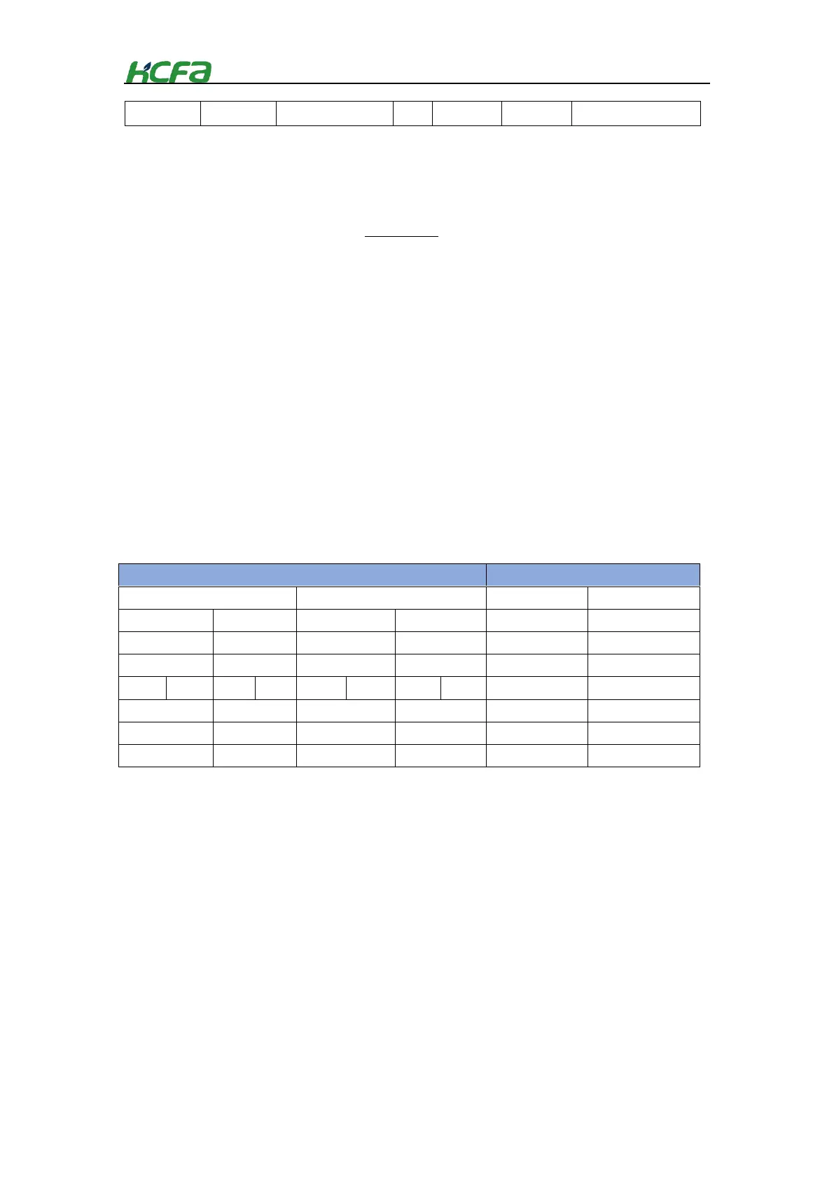
Table 0-2 Relationship between I/O signal and value display
 Loading...