Operating Instructions • AT2000 CPK • 07-2019 • v03 • 106-29004
Design and function
10
3.2 Functional description
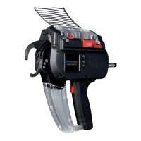
3.2.1 AT2000 CPK
8 6 5 47
13
3
2
11
12
10
9
1
1 Actuator service flap left
2 Actuator bandoleer cutter
3 Socket for connection to power pack
4 Enter button to confirm a selection in the navigation menu and increment switch
for display settings
5 Select and reset button for selecting a menu for display settings
6 LED status indicator
7 Start trigger
8 Box for waste material
9 Display with touch-sensitive controls
10 Front cap with level sensor, upper and lower jaws
11 Catch
12 Drum
13 Cable tie bandoleer
The AT2000 CPK is an electrically powered system for
bundling electrical wires, for example, and for securing
parts of various kinds with T18RA cable ties, 100mm ×
2.5mm × 1mm (L×W × H).
Force and quality of the binding can be software-
controlled or set by means of the display on the device,
à"Operation" on page11.
The items to be bundled have to be positioned between
the jaws and against the front cap. The device then
closes the tie as soon as the trigger is pressed.
If a fault occurs, messages appear on the display to
guide the user through the recommended fault-
diagnosis routine, à"Troubleshooting" on page29.
Process data of various kinds are collected during use.
These data can be analysed by PC software and used to
document process capability, for example. In addition,
the operator is notified if the tension force exceeds the
preset, à"HT Data Management" on page17.
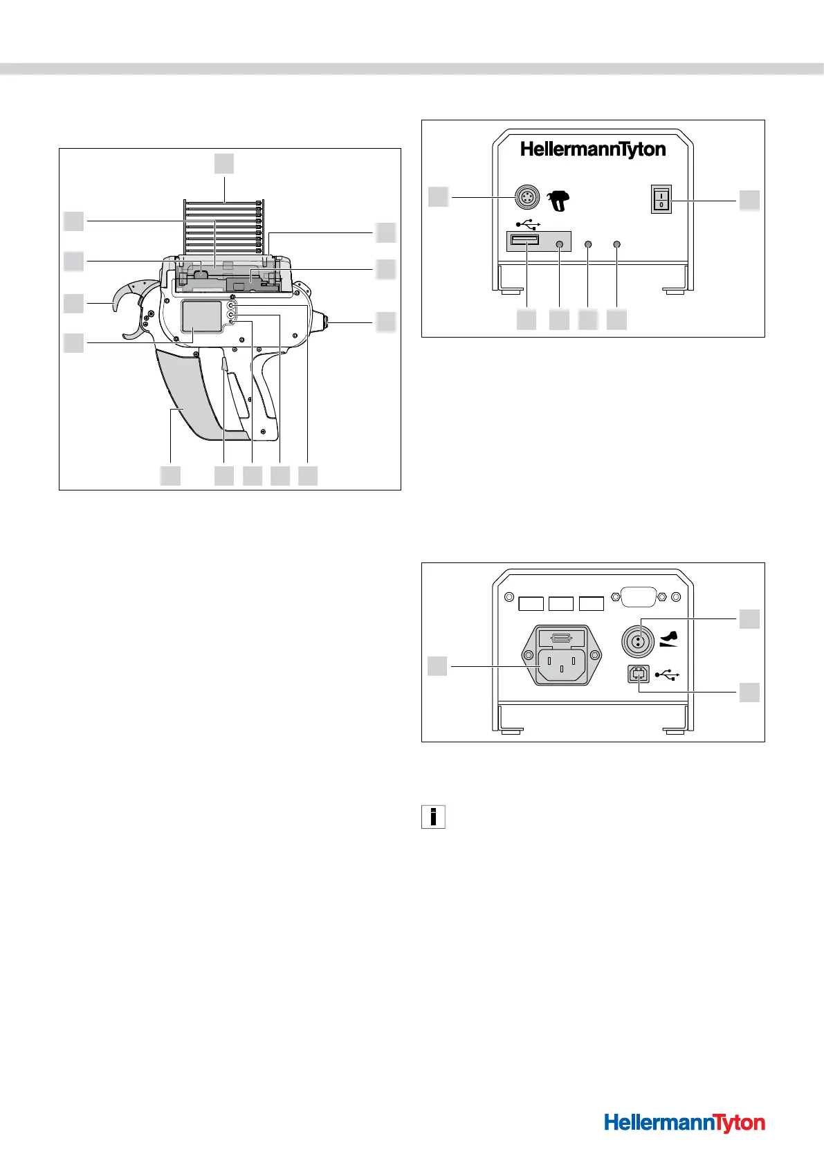
3.2.2 Power pack CPK
Data Signal Power
Power pack CPK
6
2345
1
1 Main switch
2 LED indicator Power:
Green: Power pack ON
3 LED indicator Signal:
Green: AT2000 CPK connected and ready,
Red: Fault
Yellow: Binding cycle active
Blue: Navigation in main menu, binding not possible
4 LED indicator Data:
Green: PC connected; AT2000 CPK connected; USB stick found; USB stick can be
removed,
Red/blue flashing: Data are being written to USB stick
5 USB port for exporting process data to USB memory stick
6 Socket for connection to AT2000 CPK
max. 250V~
In: Last Tie
Out: Error
Out: Busy
Serial port
3
1
2
1 Socket for foot pedal
2 USB port for connection to PC (for the HTDM)
3 Socket for power supply
In automatic systems, the AT2000 CPK can be integrated
with the separate power pack with control box (106-00110)
via a serial interface.
.