Operating Instructions • AT2000 CPK • 07-2019 • v03 • 106-29004
Settings in the display menu
12
6.4 Positioning and binding items for bundling
f Select the Force level and/or Quality parameters,
à"Accessing the parameter set" on page13 or
à"Select parameter set" on page19.
f Check the time and date; set if necessary,à"Date /
time" on page16.
The device is suitable for the following bundle
geometries:
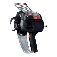
42 mm
20 mm
1
2
3
The distance from front cap 1 to flat 2 must be at least
42mm. Bundle 3 can be no more than 20mm in
diameter.
CAUTION
Crush hazard when jaws close.
f Do not insert fingers between upper and lower jaws and
do not keep your finger on the trigger.
f Always keep the power pack switched OFF when
clearing a blockage.
1
3
2
f Centre the bundle 1 in line with front-cap screws 3 .
Space adjacent cable ties at least 10mm apart.
f Press the trigger
2 .
; The bundle
1 is secured by the cable tie.
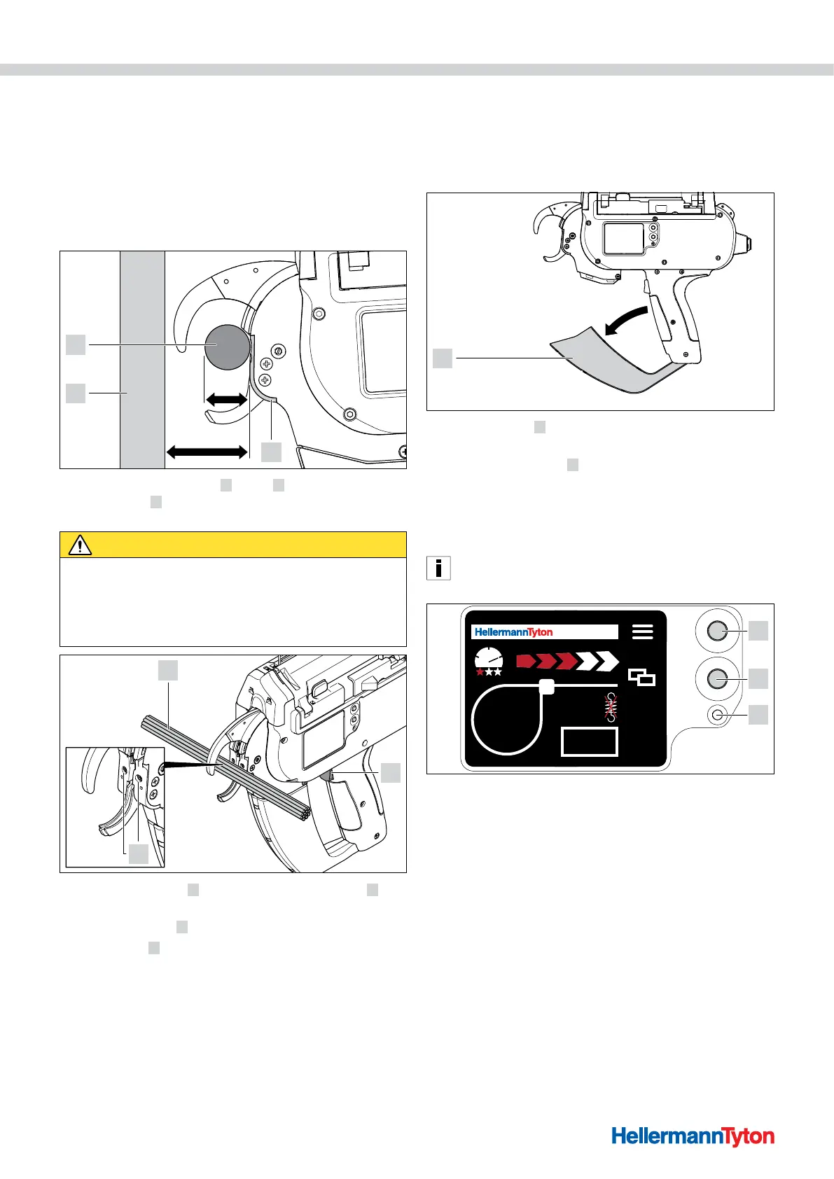
6.4.1 Emptying the waste box
The waste box has to be emptied after a maximum of
120 bindings at a bundle diameter of 3mm. As the
bundle diameter increases, so does the number of
bindings until the waste box has to be emptied.
f Pull waste box 1 in the direction indicated by the arrow
and empty the box.
f Close the waste box
1 .
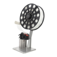
7 Settings in the display menu
After switching on the AT2000 CPK at the connected
power pack, the start screen appears on the display.
The additional device functions (e.g. clock time) are
configured on the main menu, à"Settings in the main
menu" on page15.
AT 2000 CPK
001
1
3
2
1 Enter button to confirm a selection in the navigation menu and increment switch
for display menu settings
2 Select and reset button for AT2000 CPK settings in the display menu
3 LED status indicator Signal:
Green: AT2000 CPK connected and ready
Red: Error
The functions for setting the bindings with the AT2000 CPK
can be directly accessed and configured in the display menu.
These include:
• Parameter set
• Force level
• Binding quality
• Loop diameter
• Cutting mode
• Cut with the tension released