4.2 HI/LO Actuator
Chapter 4: Removal, Replacement, and Adjustment Procedures
Page 4 - 6 Electrically Operated General Ward Bed
Operation and Maintenance Manual (154588 REV 1)
8. Disconnect the cable-to-control box connection as required to allow the
actuator to be removed from the bed.
The type of cable from the actuator will vary depending on the configuration
and date of manufacture.
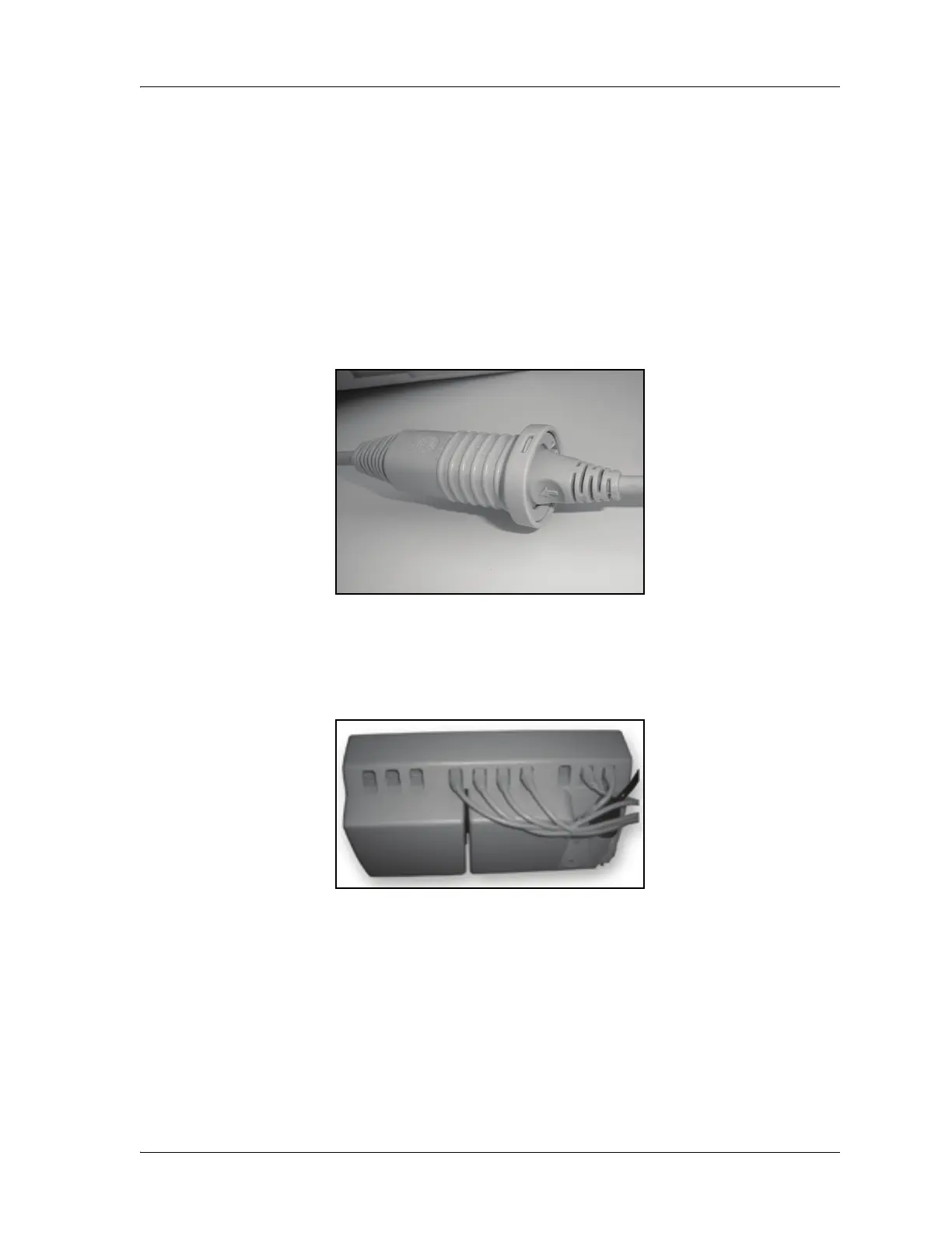
9. Remove the retaining clip, and unplug the in-line socket (see figure 4-6 on
page 4-6).
Figure 4-6. Mini-Fit Cable Configuration
– For hard-wired configurations, access the sockets by removing
the saddle. Use a flat screwdriver to pry in a downward direction
(see figure 4-7 on page 4-6).
Figure 4-7. Hard-Wired Cable Configuration
 Loading...