4.2 HI/LO Actuator
Chapter 4: Removal, Replacement, and Adjustment Procedures
Electrically Operated General Ward Bed Page 4 - 7
Operation and Maintenance Manual (154588 REV 1)
4
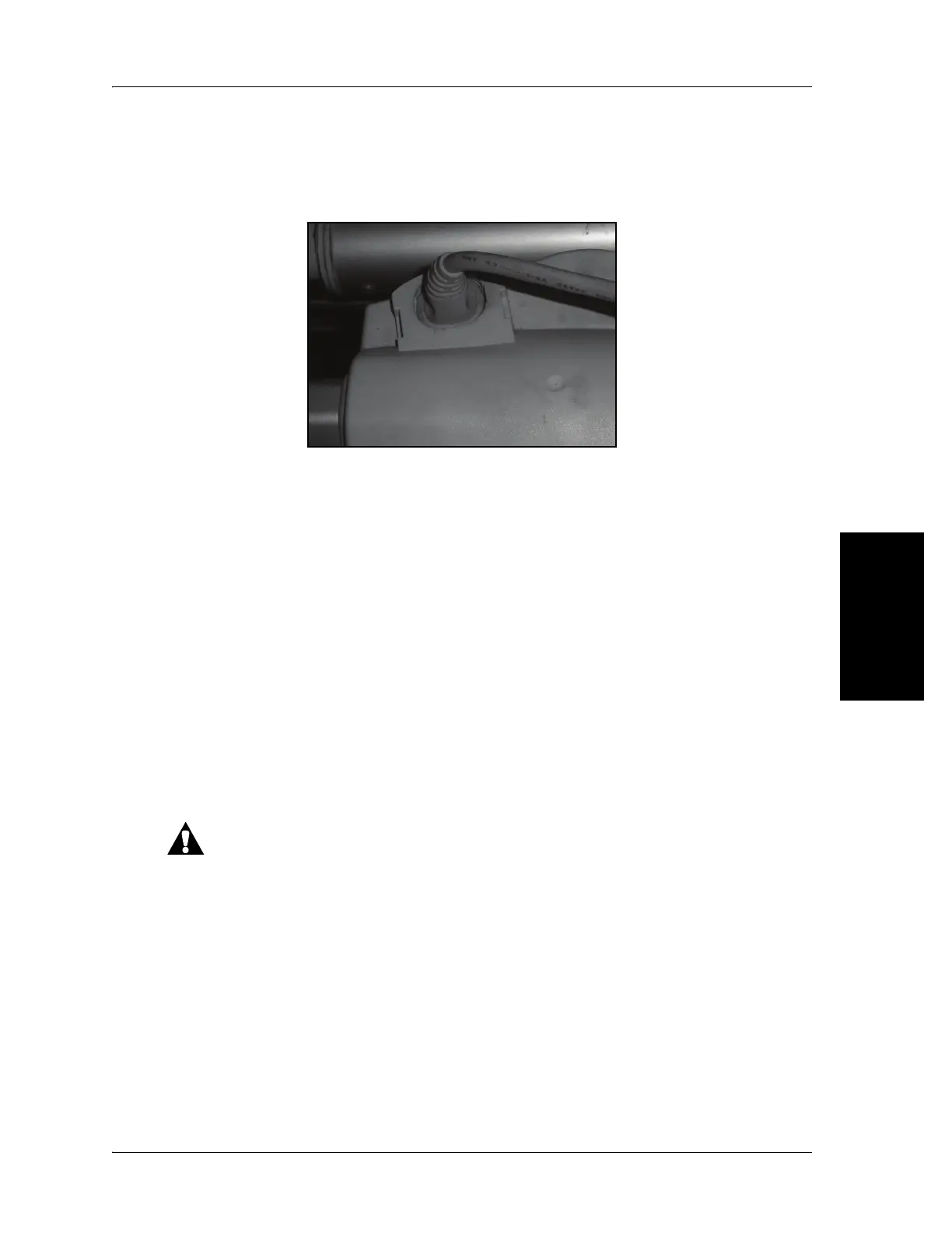
– For plug-in type configurations, unplug the cable directly at the
actuator (see figure 4-8 on page 4-7).
Figure 4-8. Plug-in Cable Configuration
In addition to the control box cable above, some systems may include SLS
limit switches. Please make note of the position of these switches before
removing them from the bed. The switches must be replaced in the same
configuration (one switch at either end of the swing mechanism).
10. Remove the mounting pins on both ends of the actuator. If the pins are
difficult to remove, the mattress frame may not be fully braced (refer to
step 4 on page 4-4).
11. Remove the actuator from the bed.
Replacement
1. Reverse this procedure to install the replacement actuator.
Cable routing, clamps and cable ties must be replaced as per the
original installation. Failure to install items correctly can cause damage
to the cables.
2. Do the “Function Checks” on page 2-3.
 Loading...