4.3 Backrest Actuator
Chapter 4: Removal, Replacement, and Adjustment Procedures
Electrically Operated General Ward Bed Page 4 - 9
Operation and Maintenance Manual (154588 REV 1)
4
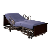
– For mini-fit configurations, remove the retaining clip and unplug
the in-line socket (see figure 4-9 on page 4-9).
Figure 4-9. Mini-Fit Cable Configuration
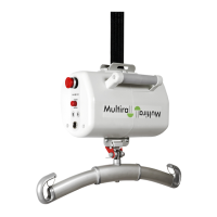
– For hard-wired configurations, access the sockets by removing
the saddle. Use a flat screwdriver to pry in a downward direction
(see figure 4-10 on page 4-9).
Figure 4-10. Hard-Wired Cable Configuration
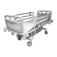
– For plug-in configurations, unplug the cable directly at the
actuator (see figure 4-11 on page 4-9).
Figure 4-11. Plug-In Cable Configuration
 Loading...