System Manual Compact Systems 7 Start-Up
HI 800 141 E Rev. 2.02 Page 63 of 110
To get additional options for programming fault reactions in the user program, assign global
variable to AO.Error Code and Module Error Code. Refer to the manual of the compact system
or module for more details.
7.3.5 Configure Line Control
The pulse delay for line control is the time between setting the pulsed outputs to FALSE and the
latest possible reading of the signal on the corresponding input.
The default value is set to 400 μs. This value might need be increased if longer wires are used.
The maximum value is 2000 μs.
The minimum time for reading all inputs results in
pulse delay x number of pulses.
The pulsed outputs are usually set to TRUE and change to FALSE in succession for the
duration of the pulse delay once per cycle.
7.3.5.1 Required Variables
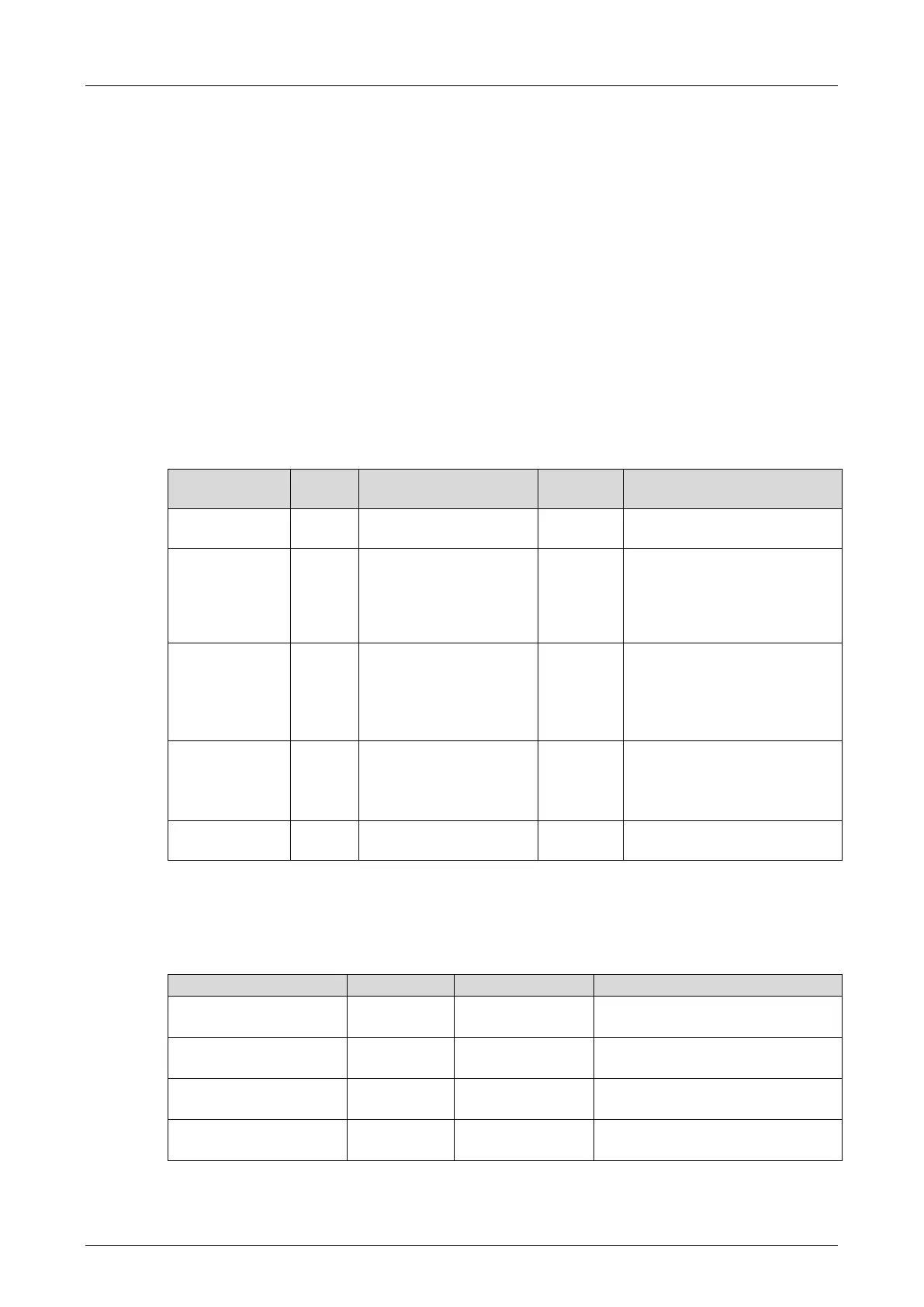
The following parameters must be created as global variables in the SILworX Global Variable
Editor:
Module slot with pulsed
outputs
With compact devices, the
DOs are used in slot 1, 2 or
3, see Table 37.
With the F60, the slot (3...8)
is given.
Value in µs
Maximum value: 2000 µs
F20: Pulse delay must be ≥
500 µs.
Refer to the F20 manual.
Pulse 1
Pulse 2
...
Pulse 8
Pulse 1...8, as required, must
match the number of pulsed
outputs.
Initialization value for
pulsed outputs
Activation of pulsed outputs
Table 35: Parameters for Line Control
The signal can be named freely; the names used in this manual are examples. All parameters
have the Const attribute.
The following table specifies the switch variables used in the example:
First and second contact of
switch 1
First and second contact of
switch 2
FC_S1_1_pulsed
FC_S1_2_pulsed
Error codes for first and second
contact of switch 1
FC_S2_1_pulsed
FC_S2_2_pulsed
Error codes for first and second
contact of switch 2
Table 36: Switch Variables for Line Control