7 Start-Up System Manual Compact Systems
Page 64 of 110 HI 800 141 E Rev. 2.02
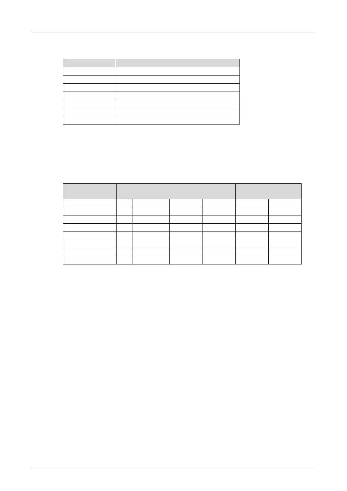
The following table specifies the slot numbers of modules with pulsed outputs when compact
devices are used.
DI Pulse Slot system parameter
Table 37: Module Slot with Pulsed Outputs
If the modular F60 system is used, the number of the slot in which the module with pulsed
outputs is inserted, must be used (3…8).
7.3.5.2 Configuring Pulsed Outputs
The pulsed outputs must begin in SILworX with channel 1 and reside in direct sequence, one
after the other.
Examples of permitted configurations ...
Table 38: Configuration of Pulsed Outputs
The corresponding inputs can be freely selected, i.e., two consecutive pulsed outputs need not
be assigned to two adjacent inputs.
Restriction:
Two adjacent inputs may not be supplied from the same pulse to prevent crosstalk.
7.3.5.3 Configuration Example with SILworX
Fundamental Method for Assigning Variables
In SILworX, the global variables previously created in the Global Variable Editor are assigned to
the individual hardware channels.
Assigning hardware channels global variables
1. Select Hardware in the structure tree of the project.
2. Right-click the input module and select Detail View from the context menu.
3. Change to the DI XX: Channels tab.
4. Drag the global variables onto the inputs to be used.
5. To assign the variables to the outputs, select the corresponding output module and proceed
as described for the inputs.
The hardware channels are assigned global variables.
The following example is based on the list provided in Table 35 and the procedure described
above.