System Manual Compact Systems 7 Start-Up
HI 800 141 E Rev. 2.02 Page 79 of 110
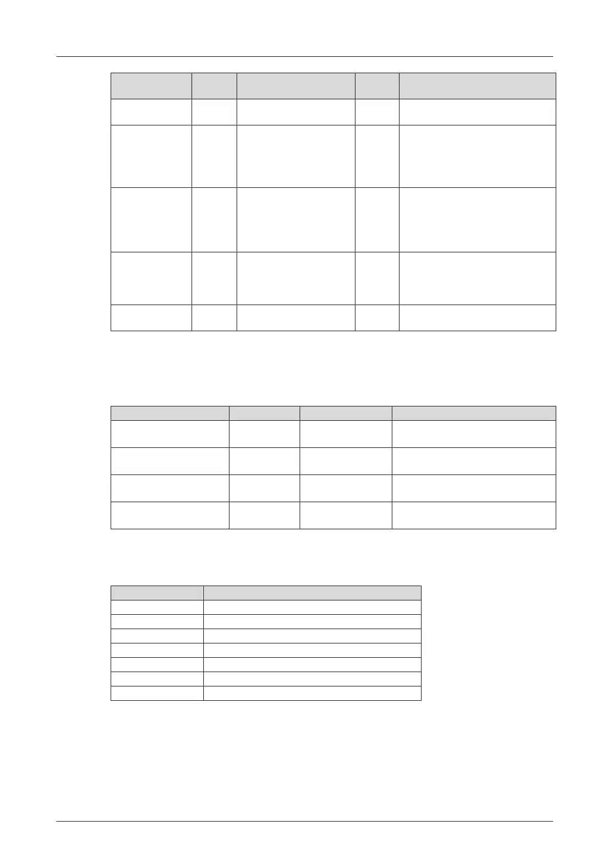
Module slot with pulsed
outputs
With compact devices, the DOs
are used in slot 1, 2 or 3, see
Table 37.
With the F60, the slot (3...8) is
given.
Value in µs
Maximum value: 2000 µs
F20: Pulse delay must be ≥ 500
µs.
Refer to the F20 manual.
Pulse 1
Pulse 2
...
Pulse 8
Pulse 1...8, as required, must
match the number of pulsed
outputs.
Initialization value for
pulsed outputs
Activation of pulsed outputs
Table 49: Signals for Line Control
The signal can be named freely; the names used in this manual are examples. All signals have
the Const attribute.
The following table specifies the switch signals used in the example:
First and second contact of
switch 1
First and second contact of
switch 2
FC_S1_1_pulsed
FC_S1_2_pulsed
Error codes for first and second
contact of switch 1
FC_S2_1_pulsed
FC_S2_2_pulsed
Error codes for first and second
contact of switch 2
Table 50: Switch Signals for Line Control
The following table specifies the slot numbers of modules with pulsed outputs when compact
devices are used.
System signal DI Pulse Slot.
Table 51: Module Slot with Pulsed Outputs
If the modular F60 system is used, the number of the slot in which the module with pulsed
outputs is inserted, must be used (3…8).
7.7.4.2 Configuring Pulsed Outputs
The pulsed outputs must begin with DO[01].Value and reside in direct sequence, one after the
other: