7 Start-Up System Manual Compact Systems
Page 80 of 110 HI 800 141 E Rev. 2.02
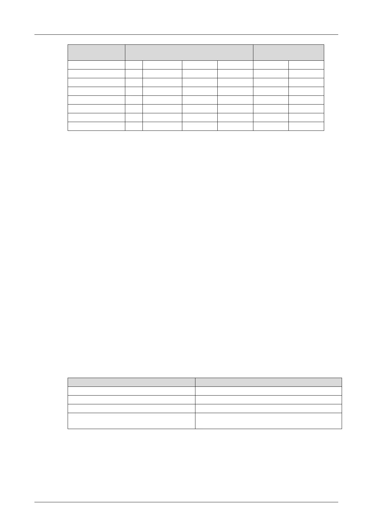
Examples of permitted configurations ...
Table 52: Configuration of Pulsed Outputs in ELOP II Factory
The corresponding inputs can be freely selected, i.e., two consecutive pulsed outputs need not
be assigned to two adjacent inputs.
Restriction:
Two adjacent inputs may not be supplied from the same pulse to prevent crosstalk.
7.7.4.3 Configuration Example with ELOP II Factory
Basic Method for Assigning Signals
If ELOP II Factory is used, the signals previously defined in the Signal Editor (Hardware
Management) are assigned to the individual hardware channels (inputs and outputs).
To connect signals to inputs and outputs
1. Select the Signals menu option to open Signal Editor of the ELOP II Factory's Hardware
Management.
2. Right-click the HIMatrix I/O module and select Connect Signals from the context menu.
A dialog box for connecting the signals in the Signal Editor to the available hardware
channels appears and contains the tabs Inputs and Outputs.
3. If required, select the Inputs tab.
4. Position the two dialog boxes adjacently to get a better overview.
5. Drag the signals onto the inputs located in the Signal Connections pane.
6. To connect the signals to the outputs, select the Outputs tab and proceed as described for
the inputs.
The signals are connected to the inputs and outputs.
The following example is based on the list provided in Table 35 and the procedure described
above.
Configuring Pulsed Outputs and Connecting them to the Inputs
The following table shows the connection of the input module's output signals to signals:
System signal (output signal)
DI Number of Pulsed Outputs
DI[xx].Pulse Output of 4 (=Sum_Pulse)
consecutive output signals
Table 53: Connecting Signals to the Input Module's Output Signals
Digital inputs (pulsed channels) may be arbitrarily connected to the pulsed outputs depending
on the hardware configuration.
Connecting the Signals to the Inputs and Corresponding Error Codes
For each useful signal DI[xx].Value, the relevant error code must also be evaluated