System Manual Compact Systems 7 Start-Up
HI 800 141 E Rev. 2.02 Page 65 of 110
Configuring Pulsed Outputs and Connecting them to the Inputs
The following table shows the connection of the system variables in the input module's Detail
View to global variables:
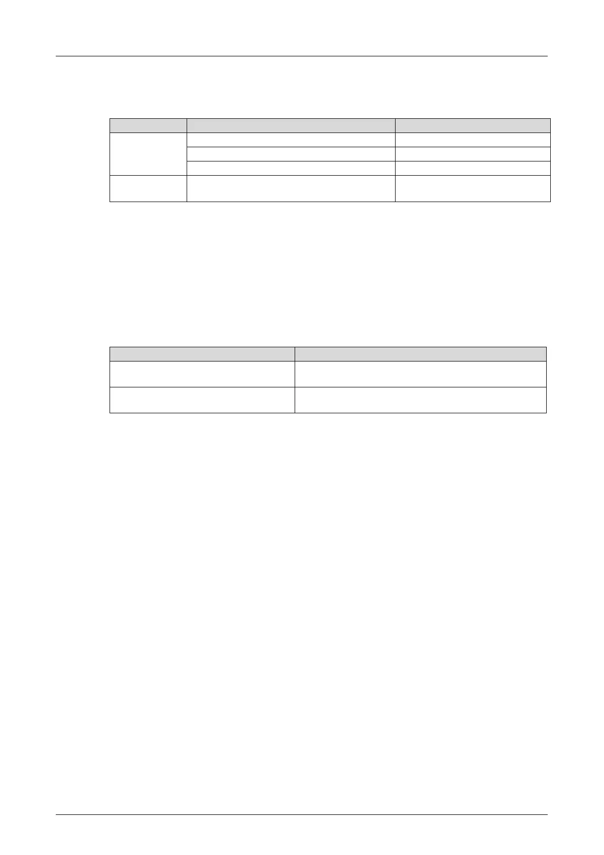
DI Number of Pulsed Outputs
Pulsed output [USINT] -> consecutive
channels from Sum_Pulse (4)
Table 39: Connection of the Global Variables to Output System Variables of the Input Module
Digital inputs (pulsed channels) may be arbitrarily connected to the pulsed outputs depending
on the hardware configuration.
Connecting the Variables to the Inputs and Corresponding Error Codes
Each input channel value -> Value [BOOL] contained in the DIxx: Channels tab located in the
input module's Detail View is allocated the corresponding error code -> Error Code [BYTE]. The
error code must be evaluated in the user program.
The following table shows the connection of the system variables in the input module's Detail
View to global variables:
-> Value [BOOL] of the corresponding
channel
S1_1_Pulsed…S2_2_Pulsed (one variable for each
channel)
-> Error Code [BYTE] of the
corresponding channel
FC_S1_1_Pulsed…FC_S2_2_Pulsed (one variable
for each channel)
Table 40: Connection of the Global Variables to Input System Variables of the Input Module
Activation of Pulsed Outputs
From the DOxx: Channels tab located in the output module's Detail View, connect the Value
[BOOL] -> system variable of every fourth successive channels (=Sum_Pulse) with Pulse_ON.
The logical value of the Pulse_ON variable is TRUE. This results in pulsed outputs that are
permanently activated and only set to FALSE for the duration of the pulse actuation.
7.3.6 Generating the Resource Configuration
With the following procedure, the code is generated twice and the resulting CRCs are compared
with one another.
To generate the code for the resource configuration
1. Select the resource in the structure tree.
2. Click the Code Generation button located on the Action Bar or select Code Generation on
the context menu.
The Code Generation <Resource Name> dialog box appears.
3. Select CRC Comparison on the Code Generation <Resource Name> dialog box (default
value).
4. In the Start Code Generation dialog box, click OK.
An additional Start Code Generation appears, shows the progress of the two code
generation processes and is closed again. The logbook contains one row informing about
the code generation result and one row reporting the result of the CRC comparison.
A valid code is generated for the resource configuration.