10 Troubleshooting
Checking procedure for main parts
SMGB0136 rev.0 - 07/2021
320
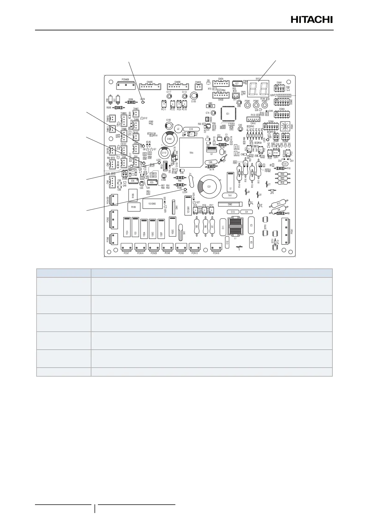
Printed circuit board for control: PCB1
LED6
LED2
LED3
LED1
LED4
SEG1
Part name Contents of functions
LED1 (Red)
Power source indicator for main board (Low Voltage).
Normal condition: Activated / ON. Abnormal condition: Deactivated / OFF.
LED2 (Green)
It indicates the communication state between the Main Board and Driven Board.
Normal condition: Flashing. Abnormal condition: Deactivated / OFF.
LED3 (Yellow)
It indicates the communication state between the indoor unit and outdoor unit.
Normal condition: Flashing. Abnormal condition: Deactivated / OFF.
LED4 (Red)
Power source indicator for Outdoor Unit PCB (280VDC).
Normal condition: Activated / ON. Abnormal condition: Deactivated / OFF.
LED6 (Red)
Power source indicator for Outdoor Unit PCB (from PCB2).
Normal condition: Activated / ON. Abnormal condition: Deactivated / OFF.
SEG1 It indicates: “Alarm”, “Protective Safety Device has Tripped” or “Checking Items”.