10 Troubleshooting
Checking procedure for main parts
SMGB0136 rev.0 - 07/2021
321
10
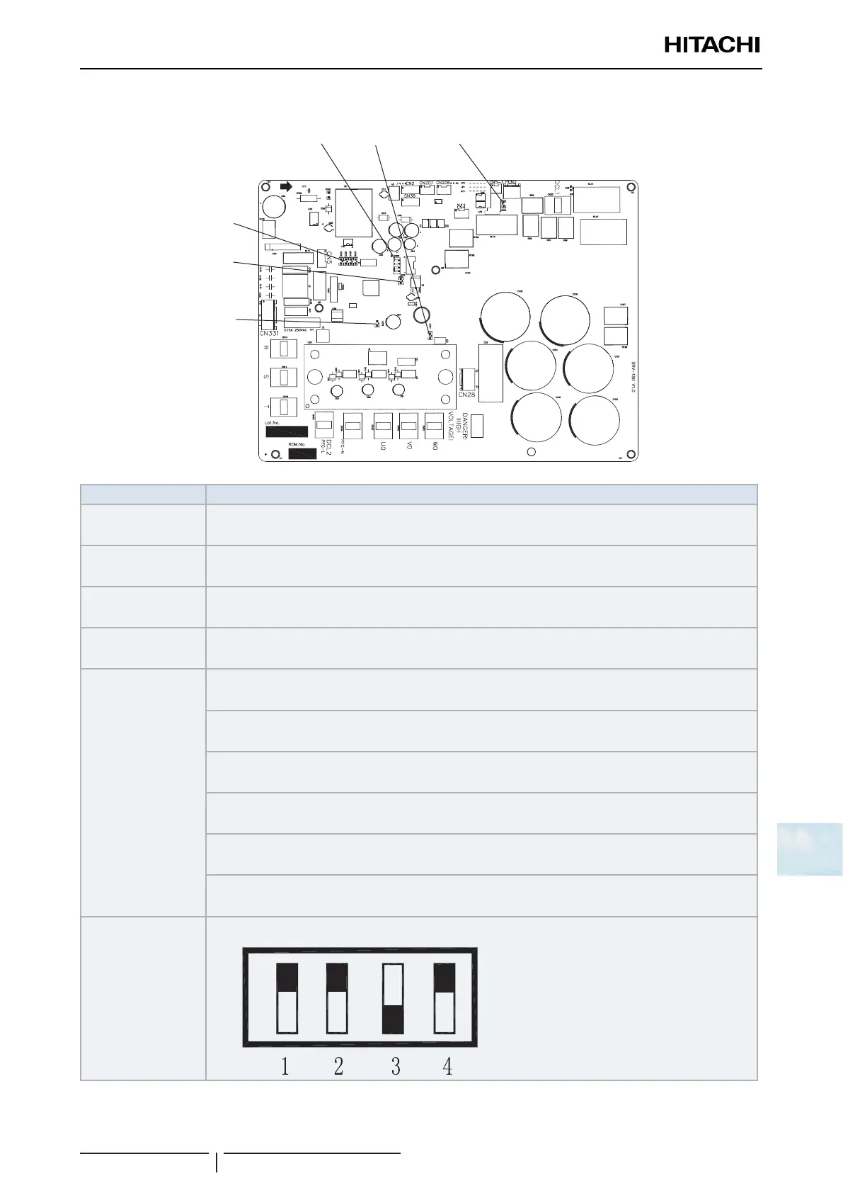
Inverter printed circuit board for control: PCB2
LED1
LED2
LED3
LED4
LED5
LED7
LED6
DSW1
Part name Contents of functions
LED1 (Green)
Communication Indicator.
Normal condition: Flashing. Abnormal condition: ON / OFF.
LED7 (Red)
Power Source Indicator for Driver Board
Normal condition: Activated / ON. Abnormal condition: Deactivated / OFF.
LED5 (Green)
Power Source Indicator for Control Part.
Normal condition: Activated / ON. Abnormal condition: Deactivated / OFF.
LED6 (Red)
Power source indicator for Precharge Relay.
Normal condition: Activated / ON. Abnormal condition: Deactivated / OFF.
LED4 (Green)
LED3 (Yellow)
LED2 (Red)
Compressor is Working
ON OFF OFF
Frequency Decrease for Overcurrent
ON ON OFF
Frequency Limit for Overcurrent
ON ON ON
Frequency Limit for Overheat
ON Flash OFF
Frequency Decrease for Overheat
ON Flash Flash
Compressor is Ready to Operate. (The Main Relay is Activated)
Flash OFF OFF
DSW1
No Setting is Required
? NOTE
Flash represent that the LED is ON for 0.5 second and then it is OFF for 0.5 second repeatedly.
 Loading...


