Default Eng. Code - 4567 Default User Code - 1111 (Irl) 1234 (UK)
15
RF-Contact/Sensor - Continued
!
!
!
!
Notes:
For best RF performance keep wiring away from antenna.
Only use 1 magnet per device.
Reed switches are active by default.
RF-Cx are known as RF-Contact and RF-CSx are known as RF-Inertia (even
though they have magnetic contacts too). The “x” suffix can be either W for white or
B for Brown
Current Consumption
Battery Life
Range
Frequency
Temperature
Weight
Main Dimensions
Magnet Dimensions
EN 50131-2-6
3Vdc nom. • 1400mAh • size 2/3A
Standby: 7µA
Transmit: 40mA (peak)
Typically >4 years
Line-of-sight > 400m
868Mhz
-10°C to +40°C
W=33mm H= 122mm D = 33mm
W=10mm H= 41mm D = 15mm
80g (including sensor head, battery & magnet)
Grade 2 Class II
Battery
Specifications
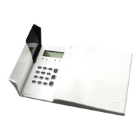
• Additional wired MC’s can wired into the system via the
Alarm/Tamper terminals. Note though, the length of the tamper
loop in this scenario is limited (100m for Alarm loop and 3m for
Tamper loop)
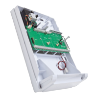
• Ensure that the inertia sensor head arrow is vertical.
• The sensor head has its own specific holder. Use the
screw holes in this holder when mounting the unit to
increase its responsiveness to vibrations.
Tamper
Loop
Alarm
Loop
+
-
LITHIUM
BATTERY
+
ULTRA LITHIUM
Mounting
Holes
 Loading...