TAMPER
TAMPER
TAMPER
TAMPER
DATA
DATA
DATA
DATA
CONTACT
CONTACT
CONTACT
CONTACT
+
+
+
+
-
-
-
-
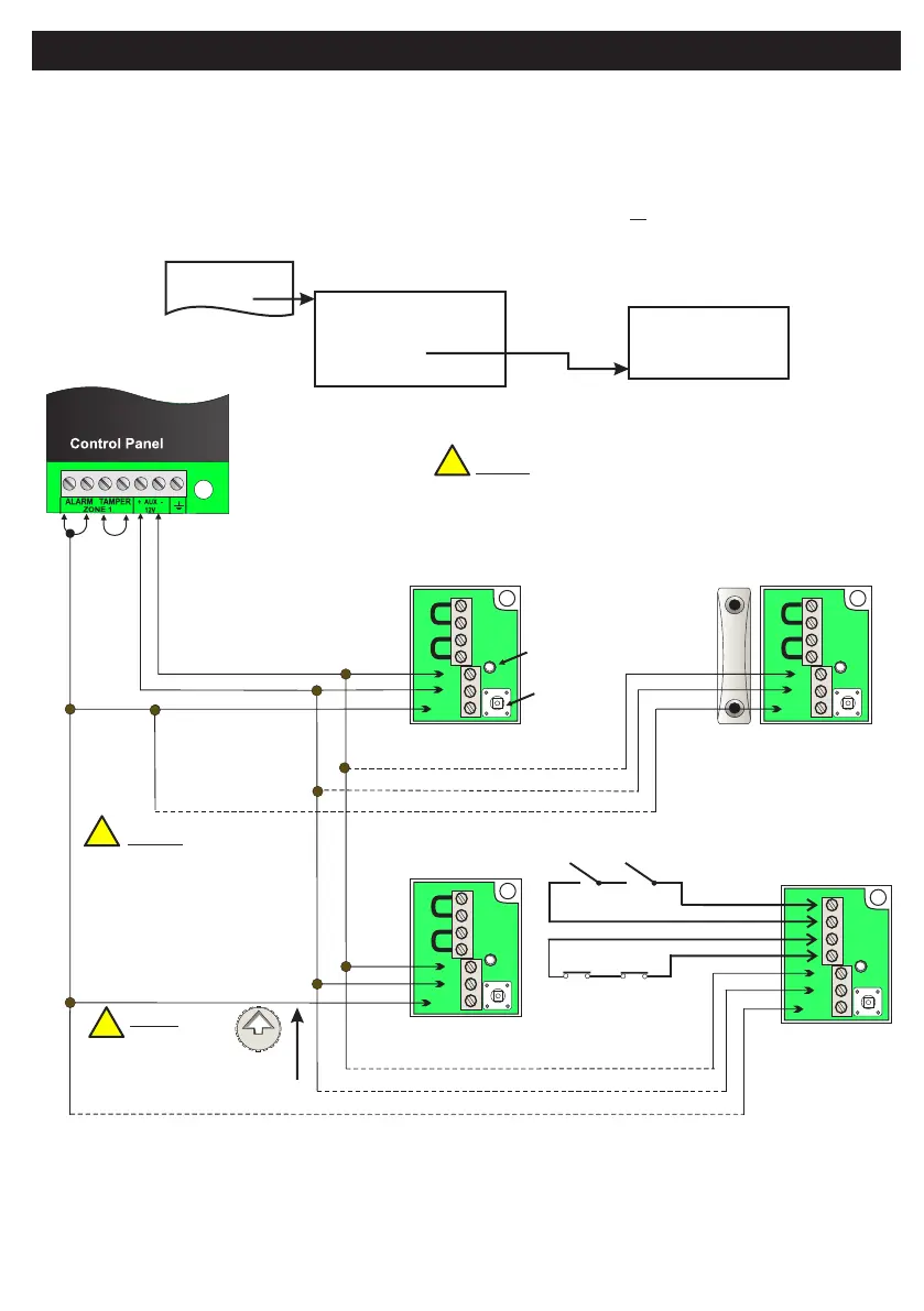
NOTE:
Please ensure that
zone terminal is
linked as shown.
Up to 10 points
can be connected
to a zone.
NOTE:
Please ensure
that sensor head
arrow is vertical
before fitting lid
BLACK
BLACK
BLUE
BLUE
BLACK
RED
RED
RED
Point ID Sensors
SENSOR 1
SENSOR 10
CONTACT
TAMPERS
BLACK
BLACK
BLUE
BLUE
BLUE
RED
RED
SENSOR 10
SENSOR 1
REED VERSION
Adding standard
senors and
contacts
Tamper Switch
Status LED
NOTE: Max. cable run to ID sensor = 200m
A total of 600m of cable can be used.
Alternatively, you can convert your hardwired zone input into a Point ID bus. This allows you to wire-in a
maximum of ten Point ID sensors
• Wire-up zone (see wiring example below).
• Leave the covers of the sensors off for now
• ,
Point ID sensors
In engineer mode scroll to the Zone Menu. Press YES and scroll to Zone Hardware. Press YES again. Scroll down
to Point ID. Then press YES. The system will automatically check the data bus for all . When the
scanning finishes, quit from this branch of the menu....
1 Zone Names
2 Zone Types
3 Zone Options
4 Zone Gross & Pulse
5 Zone Hardware
6 Zone Block Assign
7 Technical Zone Options
2 Non EOL
3 Single EOL
4 Dual EOL
5 Point ID
1 RF Device
2 Devices Menu
1 Service Menu
3 Zone Menu
Default Eng. Code - 4567 Default User Code - 1111 (Irl) 1234 (UK)
44
!
!
!