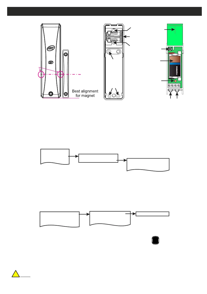
RF-Contact/Sensor
Mounting
Holes
Mounting
Hole
Mounting
Hole
Sensor
Head
Mounting
Hole for
Pry-off
Tamper
These ribs
indicate
Centre Mark
of Magnet
• >4 Years Battery Life
• >400m Line-of-sight Radio Range
• MC Switches (Reeds) on Left and Right
• Optional Inertia Sensor Version
• Adjustable Sensitivity on Inertia Sensor
• RF-CW = (magnetic Contact in white) and RF-CB = (magnetic Contact in brown)
• RF-CSW = (MC & inertia Sensor in white) and RF-CSB = (MC & inertia Sensor in brown)
2 Devices Menu
2 Wired Devices Menu
1 Add&Id:RF Zones
2 Add&Id:RF Keyfob
3 Add&Id:RF Echo
1 RF Devices Menu
1 Add & ID RF Devices
Scanning RF Devs
1 Add & ID RF Devices
2 Locate RF Devices
2 Locate RF Devices
3 Remove RF Devices
3 Remove RF Devices
1 Service Menu
3 Zone Menu
• To put an RF-Cx or RF-CSx on to a Quantum 70 system go into engineer mode.
• Open the RF-Cx or RF-CSx and pull the isolator away from the battery - this powers it up.
• If you have a number of devices you can open them too at this stage and remove their isolators.
• Don’t close their lids just yet.
• Select the Devices Menu. Then RF Devs Menu. Next select the Add & Id RF Devs option.
• Next, add and identify the RF-Cx or RF-CSx as a zone.
• The system displays Devs Found - 000 when it starts scanning and as it finds its first device the display will
change to Devs Found - 001. When the system has found all its devices, press
• Select zone number to be added & Id’ed.
• Next, close the devices’ tamper switches by fitting their lids.
• As you close the devices’ tamper switches in sequence. You will hear an audible indication as each device
is identified into the system
Note: The RF-Echo can have a delayed reaction.
PLAY
QUIT
Add & ID on to the System
!
Default Eng. Code - 4567 Default User Code - 1111 (Irl) 1234 (UK)
13
C
L
Tamper
Switch
Tamper
Loop
Alarm
Loop
Battery
Antenna
Status
LED
+
-
+
ULTRA LITHIUM
 Loading...