■ Three phase AC380V power input
Main circuit power
supply input terminal
for AC power supply
input
Three phase AC 380V~420V,-15%~+10%,50/60Hz
Control power supply
terminal
Regenerative resistor
connection terminal
HSD7DS-15D , HSD7DS-18D , Remove the short wire or short piece
between B2-B3 when the regeneration capacity is insufficient and connect the
external regeneration resistor between B1/⊗and B2.
Please purchase an external regenerative resistor separately.
HSD7DS-24D and HSD7DS-35D no built-in regenerative resistor, and
cannot be shorted between B2 and B3. External regenerative resistor shall be
connected between B1/⊗ and B2. Please purchase an external regenerative
resistor separately.
None (Do not connect it to the terminals.)
4.3.2 Wiring Operation Steps of Main Loop Connector
Prepare items
Spring opener
or
Slotted screwdriver
Spring opener
Servo drive appurtenances
Slotted screwdriver
Commercial products with cutting edge width of 3.0mm-3.5mm
1. Remove the main circuit connector and motor connector from the servo drive.
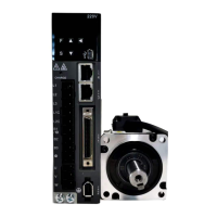
2. Peel off the cladding of the used wires.
3. Use a tool to open the wire insertion part of the terminal connector. There are two methods of opening. You
can choose any of them.
①Use method of spring opener
②Use method of flat screwdriver
The opening operation is performed using a
spring opener as illustrated
As shown in the figure, insert a flat-blade
screwdriver into the screwdriver insertion opening
to open the wire insertion part.
4. Insert the core wire part of the wire into the wire insertion part. After insertion, pull out the spring opener or a
slotted screwdriver.
5. Repeat the above operations and make necessary connections.
6. After wiring is completed, install the connector to the servo drive.
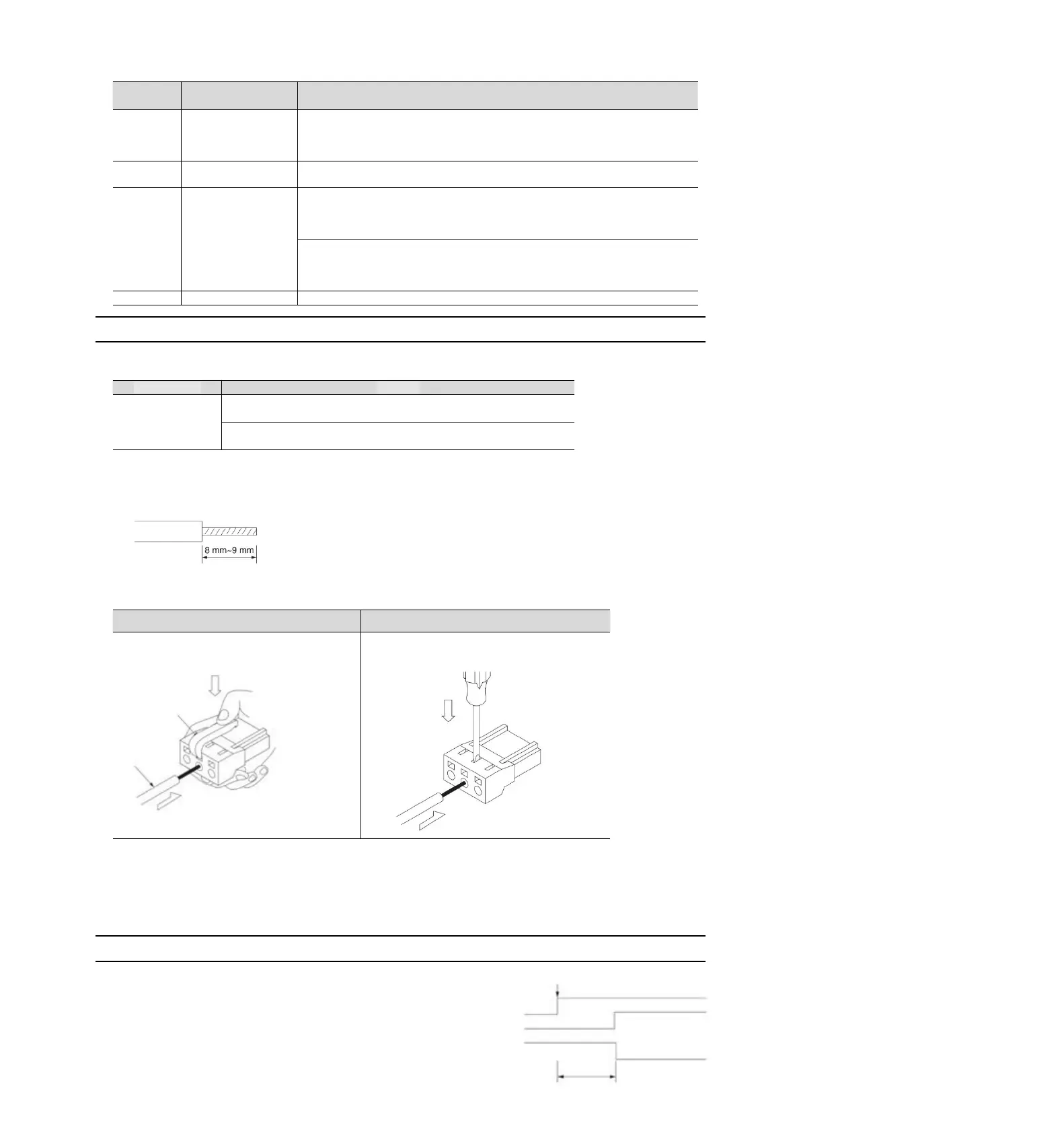
4.3.3 Power on sequence control
Please consider the following points when designing the
power on sequence control.
After the control power is turned on, the servo alarm
output (ALM) signal is output within a maximum of 5.0
seconds. Please consider it when the power on
Control power supply
Main circuit power
supply
Servo Alarm Output
(ALM) Signal