Do you have a question about the HNC Electric HSD7-E Series and is the answer not in the manual?
Indicates the document is a user's manual for the HSD7-E Series AC Servo Drive.
Identifies the publisher of the manual as HNC Electric Limited.
Explains how to effectively use the manual, including terminology and icons.
Defines key terms used throughout the manual for better understanding.
Explains the meaning and usage of icons to aid comprehension.
Details the various warning signs used to indicate hazards and precautions.
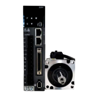
Provides fundamental information about the HSD7 series AC servo drivers.
Explains how to identify and interpret the information on the servo drive's nameplate.
Details how to understand the servo drive model designations and provides an example.
Lists the essential ratings and technical specifications for servo drive selection.
Presents detailed rating values for different servo drive models.
Provides a comprehensive table of servo drive specifications.
Displays the physical dimensions and mounting hole details for servo drivers.
Outlines important precautions to consider before installing the servo drive.
Describes the acceptable mounting types and orientations for the servo drive.
Specifies the dimensions for mounting holes required for installation.
Details the recommended spacing around the servo drive for proper cooling.
Provides essential precautions for safe and correct wiring of the servo unit.
Covers general safety guidelines and crucial steps for wiring the servo drive.
Explains methods to prevent or reduce electromagnetic interference.
Provides guidelines for proper grounding treatment to prevent misoperation.
Shows a fundamental wiring diagram for the servo drive system.
Details how to connect the power supply to the servo drive, including terminal information.
Provides step-by-step instructions for wiring the main loop connector.
Explains the considerations for designing the power-on sequence.
Illustrates the power wiring diagram for three-phase input.
Details how to connect the external regenerative resistance.
Guides on connecting the servo motor to the drive, including terminal and pin details.
Explains how to connect the servo drive to the encoder, including absolute value encoders.
Details the wiring for connecting the servo drive to the motor brake.
Covers the connection of input and output signals to the servo drive.
Lists the names, functions, and pin arrangements of the CN1 connector signals.
Provides wiring examples for input and output signals in various control modes.
Explains the input and output loops, including optocoupler and linear driver connections.
Introduces parameter classification, writing, and setting procedures.
Classifies servo drive parameters into setting and adjustment categories.
Explains the two methods for writing parameters: numerical and function selection.
Describes how parameters can be set using the panel operator or software.
Explains the function to prevent unauthorized parameter changes.
Details how to restore parameters to factory default settings.
Covers setting communication speed and station address for MECHATROLINK-II.
Covers setting communication specifications for MECHATROLINK-III.
Covers setting communication specifications for EtherCAT.
Explains how to set power supply types for the main and control circuits.
Explains how to set single-phase or three-phase AC power input.
Describes the function and setting of the servo ON signal.
Details how to set the servo to remain constantly ON.
Explains how to set the motor's rotation direction.
Covers functions and settings for over-travel prevention.
Describes the P-OT and N-OT overtravel signals.
Explains how to enable or disable the over-travel prevention function.
Details the methods for stopping the motor during over-travel events.
Describes the function to warn about over-travel conditions.
Discusses the servo motor brake function and its settings.
Explains the timing for brake opening and action.
Details the /BK signal for controlling the brake output and its distribution.
Sets the delay time for the /BK signal when the servo motor stops or rotates.
Explains methods for stopping the motor during Servo OFF or alarm conditions.
Details motor stop methods when Servo OFF occurs.
Covers motor stopping methods for Gr.1 and Gr.2 alarms.
Sets values for detecting motor overload warnings and alarms.
Explains how to adjust the detection time for overload warnings.
Details how to adjust the detection time for overload alarms.
Explains the electronic gear function for converting movement to pulses.
Covers setting the electronic gear ratio using parameters Pn20E and Pn210.
Provides examples of setting the electronic gear ratio for different mechanisms.
Guides on setting and initializing absolute value encoders.
Lists precautions and notes for initializing absolute value encoders.
Reminds users to confirm settings before initializing the absolute value encoder.
Lists the tools available for setting and initializing absolute value encoders.
Covers setting the regenerative resistance capacity and value.
Explains how to assign functions to input/output signals.
Details the distribution and parameter mapping of input signals.
Explains the distribution and assignment of output signals.
Describes the servo alarm output signal that indicates faults.
Explains the warning output signal that indicates potential issues before alarms.
Describes the signal indicating the servo motor is running.
Explains the signal indicating the servo drive is ready to receive a servo ON command.
Describes the signal output when motor speed matches the command speed.
Explains the signal indicating that positioning is complete.
Describes the signal notifying about reaching a near-positioning completion point.
Details the function for limiting motor speed during torque control.
Describes the output signal indicating motor speed limitation.
Explains how to select the speed limit value.
Explains how the servo drive operates during momentary power interruptions.
Covers the SEMI F47 specification support for voltage drops.
Explains how to set undervoltage warnings and torque limitation.
Explains how to set the maximum speed for the servo motor.
Covers the output of 2-phase encoder pulses for position feedback.
Details how to set the encoder frequency division pulse count (Pn212).
Outlines the general process for commissioning the servo motor test run.
Lists the sequential steps for conducting a servo motor test run.
Provides essential inspection items and precautions before commissioning.
Guides the commissioning process for the servo motor unit using JOG operation.
Lists confirmations required before executing JOG operation.
Lists executable tools for JOG operation, such as panel operator and software.
Introduces the panel display and operator keys.
Details the names and functions of the panel operator keys.
Explains how to switch between different operating modes on the panel.
Describes how to interpret the status displayed on the panel.
Explains the meaning of different bit data displays on the panel.
Explains the meaning of thumbnail symbols shown on the display.
Guides on operating parameters using the panel operator.
Details how to set parameters using the numerical setting type.
Explains how to set parameters using the function selection type.
Describes how to use the monitor display on the panel operator.
Lists various monitoring and display functions available.
Explains the basic operations for using the monitoring display.
Details how to monitor input and output signals on the panel operator.
Guides on using auxiliary functions via the panel operator.
Lists available auxiliary functions for execution.
Explains how to display alarm records using the panel operator.
Details how to perform JOG operation using the panel operator.
Guides on performing origin search using the panel operator.
Explains how to run a program JOG using the panel operator.
Details how to initialize parameter settings via the panel operator.
Explains how to delete alarm records using the panel operator.
Guides on setting up and initializing the absolute value encoder.
Explains automatic adjustment of analog command bias.
Details manual adjustment of speed command bias.
Explains manual adjustment of torque command bias.
Covers automatic adjustment of motor current detection signal offset.
Explains how to set write inhibit for parameters.
Details how to display the motor model information.
Explains how to display the servo-driven software version.
Guides on performing single parameter adjustments.
Explains the EasyFFT function for analyzing vibration characteristics.
Details the function for detecting load inertia and mass.
Covers inspection procedures and component replacement.
Outlines the inspection items that need to be checked annually.
Explains how to replace the battery when voltage is low.
Details settings for battery undervoltage alarms and warnings.
Explains how alarm numbers are displayed on the panel.
Lists warnings, their causes, and treatment measures.
Provides a detailed table of alarm causes and corresponding treatment measures.
Explains methods for resetting servo alarms.
Describes the function to display recorded alarms.
Explains how to delete alarm records.
Provides information on handling warnings displayed on the drive.
Lists warnings, their contents, and reset information.
Lists causes for warnings and provides corresponding countermeasures.
Explains how to monitor command data when alarms or warnings occur.
Provides methods to diagnose faults based on servo motor behavior.
Provides a comprehensive list of servo parameters.
Explains how to interpret the parameter list format.
Continues the detailed listing and description of servo parameters.
Details the steps for connecting and logging into the iWath+ debugging software.
Explains the automatic adjustment function without upper device commands.
Continues describing automatic adjustment, including confirmation and operating steps.
Provides detailed steps and settings for auto-tuning using iWatch+.
| Category | Servo Drives |
|---|---|
| Series | HSD7-E |
| Control Mode | Torque, Speed, Position |
| Communication Interface | CANopen |
| Protection Features | Overvoltage, Undervoltage, Overcurrent, Overtemperature, Short Circuit |
| Operating Temperature | 0°C to 55°C |