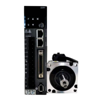
The "forward rotation direction" set by the factory is "counterclockwise rotation (CCW)" as viewed from the
load side of the servo motor.
Motor rotation direction and encoder frequency division
pulse output
n. 0 the
CCW direction
is the forward
rotation
direction.
Factory
setting]
Prohibit
positive
rotation side
drive input
(P-OT) signal
Disable
reverse side
drive input
(N-OT) signal
n. 1 the
CW direction
is the forward
rotation
direction.
Reverse
Mode)
Prohibit
positive
rotation side
drive input
(P-OT) signal
Disable
reverse side
drive input
(N-OT) signal
5.8 Functions and settings of over-travel prevention
The over-travel prevention function of servo drive refers to the safety function of forcing the servo motor to
stop by inputting the signal of limit switch when the movable part of the machine exceeds the designed safe
movement range.
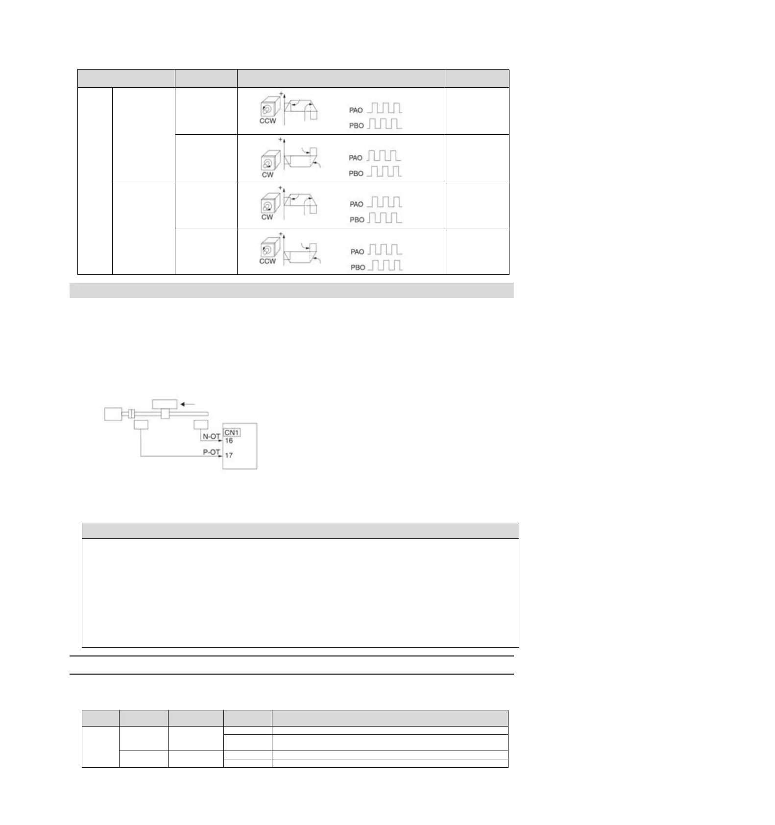
The overtravel signal includes a P-OT signal that prohibits forward rotation and an N-OT signal that prohibits
reverse rotation. The P-OT and N-OT signals are used to set a limit switch at the position to be limited when
starting the machine under the drive of the servo motor, and then stop the machine through the signals.
Examples of servo drive wiring are shown below.
Rotary applications such as round tables and conveyors do not require over-travel prevention function, and
there is no need to wire the over-travel prevention input signal at this time. The following is a description of the
parameter setting related to the over-travel prevention function.
In order to prevent accidents caused by poor contact and disconnection of contact parts, please use "normally closed
contact" for limit switches.
In addition, do not change the factory setting of the polarity of over-travel signals (P-OT, N-OT).
When the servo motor is used as a vertical shaft, the brake control output (/BK) signal will remain in the ON (brake
on) state in the overtravel state, so the workpiece may fall off when overtravel occurs. In order to prevent the
workpiece from falling off, please set it to a zero fixed state after the servo motor stops (Pn 001 = n.1).
In case of overtravel, it will enter the base blocking state after stopping, but it may be dragged back when the load
shaft side receives external force. In order to prevent the servo motor from being dragged back due to external force,
please set it to a fixed zero position after the servo motor stops (Pn 001 = n.1).
5.8.1 Overtravel signal
The overtravel signal includes a P-OT signal that prohibits forward rotation and an N-OT signal that prohibits
reverse rotation.
Forward-turning side can be driven (normal operation)
It is forbidden to drive the forward rotation side (forward rotation
side over travel)
The reverse side can be driven (normally operated)
Reverse side drive is prohibited (reverse side overtravel)
Encoder frequency division
pulse output
Encoder frequency division
pulse output
Encoder frequency division
pulse output
Encoder frequency division
pulse output
Motor forward rotation direction