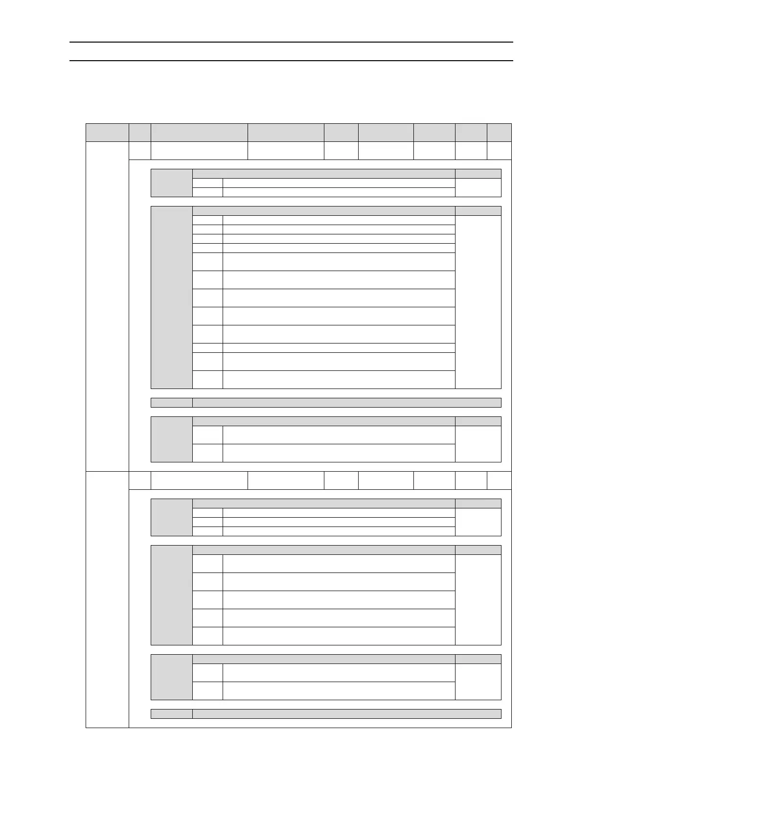
10.1.2 List of servo parameters
The parameter list is as follows.
(Note) The following parameters are factory settings and should not be changed.
• Appointment Parameters
• Parameters not recorded in this manual
Function selection Basic
switch 0
Rotation direction selection
The CCW direction is the forward rotation direction.
The CW direction is the forward rotation direction. (Reverse mode)
Speed control (analog command)
Position control (pulse sequence command)
Rotational moment control (analog command)
Internal set speed control (contact command)
Internal set speed control (contact command)
speed control (analog
command
Internal set speed control (contact command)
position control
(pulse sequence command)
Internal set speed control (contact command)
torque control
(analog command
Position control (pulse sequence command) speed control (analog
command)
Position control (pulse sequence command) torque control (analog
command)
Torque control (analog command) speed control (analog command)
Speed control (analog command)
speed control with zero position
fixing function
Position control (pulse sequence command)
position control with
command pulse disable function
Appointment parameters (do not change it)
Startup selection when encoder is not connected
It is started as the corresponding servo drive of the rotary servo motor
when the encoder is not connected.
It is started as the corresponding servo drive of the linear servo motor
when the encoder is not connected.
Function selection
application switch 1
Servo OFF and Stop Method in Gr.1 Alarm
Stop the motor by DB (dynamic brake).
Stop the motor through DB, and then cancel DB.
Do not use DB, set the motor to run freely.
Stop Method when it is overtravel (OT)
DB stop or free running stop (stop method is the same as Pn001=
n.X).
The set torque of Pn406 is used as the maximum torque to decelerate
and stop the motor, and then the servo lock state is entered.
The set torque of Pn406 is taken as the maximum torque to decelerate
and stop the motor, and then enter the free running state.
According to the deceleration time of Pn30A, the motor decelerates
and stops, and then enters the servo locking state.
According to the deceleration time of Pn30A, the motor will decelerate
and stop, and then enter the free running state.
Selection of AC/DC input for main loop power supply
AC power is input from L1, L2, L3 and L3 terminals as the main loop
power (no universal converter is used).
Between B1/⊕, ⊖the input DC power supply is as the main loop
power supply (using an external converter or a universal converter).
Appointment parameters (do not change it)