Chapter 10 List of parameter
10.1 List of servo parameters
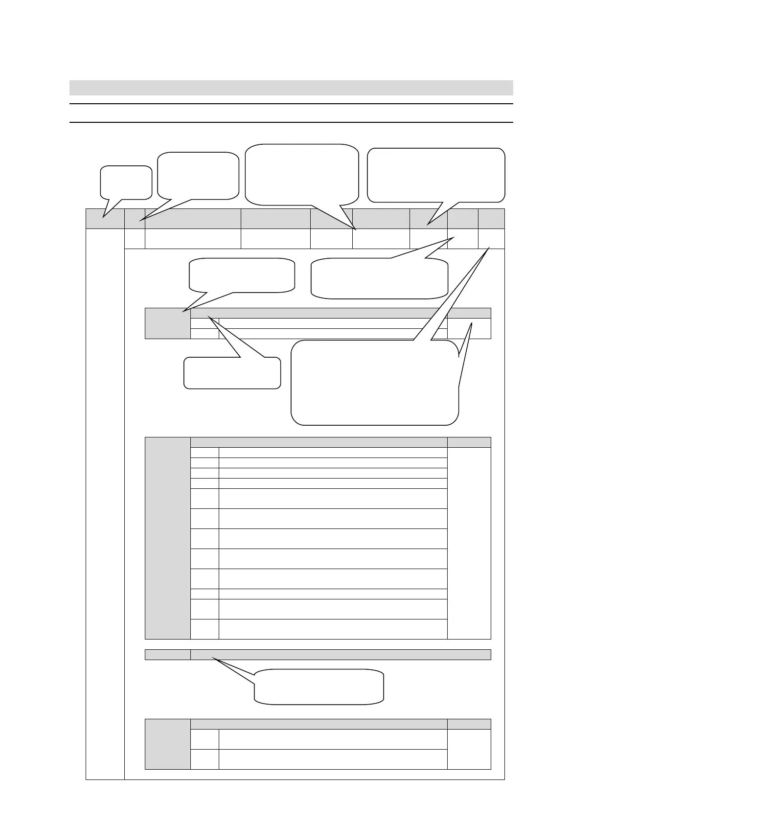
10.1.1 Method for distinguishing the list
Function selection Basic
switch 0
0010 (axis A)
0000 (axis b)
Rotation direction selection
The CCW direction is the forward rotation direction.
The CW direction is the forward rotation direction. (Reverse mode)
Speed control (analog command)
Position control (pulse sequence command)
Rotational moment control (analog command)
Internal set speed control (contact command)
Internal set speed control (contact command) speed control (analog
command
Internal set speed control (contact
command) position control (pulse
sequence command)
Internal set speed control (contact
command) torque control (analog
command
Position control (pulse sequence command) speed control (analog
command)
Position control (pulse sequence command) torque control (analog
command)
Torque control (analog command) speed control (analog command)
Speed control (analog command)
speed control with zero position
fixing function
Position control (pulse sequence command) position control with
command pulse disable function
Appointment parameters (do not change it)
Startup selection when encoder is not connected
It is started as the corresponding servo drive of the rotary servo motor
when the encoder is not connected.
It is started as the corresponding servo drive of the linear servo motor
when the encoder is not connected.
Indicates that this parameter is only valid for the corresponding
model;
P corresponds to models HSD7-A00, HSD7-D00
HSD7-A01, HSD7-D01
B corresponds to models HSD7-A10, HSD7-D10
HSD7-A20, HSD7-D20
HSD7-A30, HSD7-D30
By default, all model parameters are valid.
Represents two categories of parameters:
Setting, which means setting class parameters
Adjustment, which means adjusting class
parameters
Indicates when the parameter changes and the change
takes effect.
Power restart: It means that the parameters will not
take effect until the servo control power is turned off
and the power is turned on again.
Indicates the
number of the
parameter
Indicates the number of
bytes occupied by the
parameter
2 means 2 bytes
4 means 4 bytes
When the factory setting values of Axis A
and Axis b of the biaxial driver are
inconsistent, the upper layer represents
the factory parameters of Axis A, the
lower layer represents the factory
parameters of Axis b.
Reserved parameters cannot be modified,
otherwise the servo system may not operate
normally.
“X”
Represents a corresponding
configurable parameter bit
The function name of the
corresponding parameter bit the
following list is optional features