Chapter 6 Application function
6.1 Distribution of input and output signals
The I/O signal connector (CN1) has pre-assigned functions, but some terminals can be assigned other
functions or change polarity. Function allocation and polarity setting are performed through parameters.
The distribution of input and output signals will be described below.
6.1.1 Distribution of input signals
When the distribution of input signals is changed for use
When the polarity of each signal of the forward drive input (P-OT) and the reverse drive input (N-OT) is
changed to the factory setting, the overtravel prevention function will not operate in case of abnormality such
as signal line disconnection. When this setting has to be adopted, please be sure to make action confirmation
to ensure there is no safety problem.
When multiple signals are distributed on the same input loop, they will become exclusive OR logic, and all
input signals will act. Therefore, unexpected actions may occur.
The relationship between the input signal assigned to the pin number of the input/output signal connector
(CN1) and the parameter setting is as follows.
Forward External Torque Limit
Reverse External Torque Limit
Origin Return Deceleration Switch Input
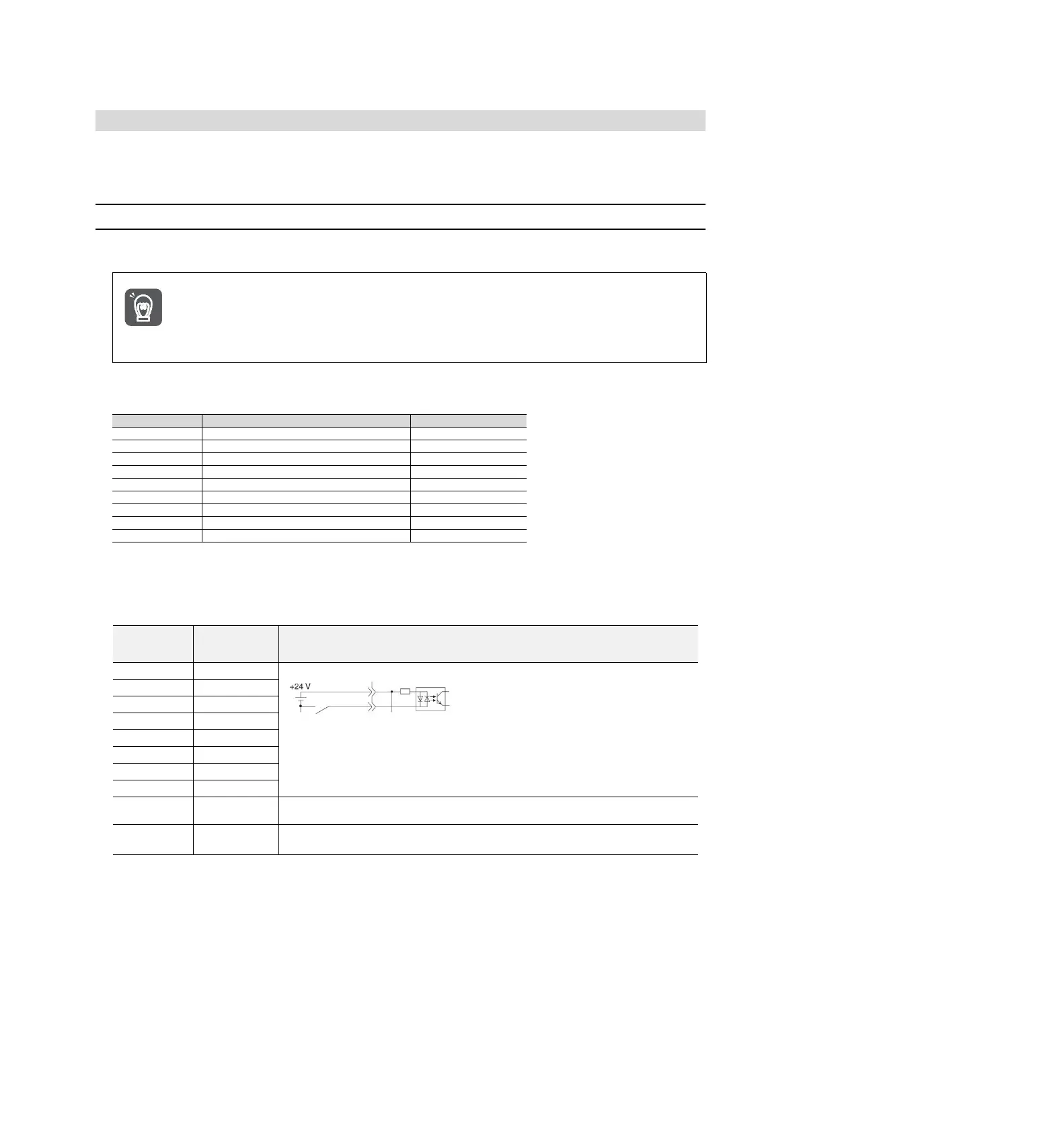
◆ Relationship between parameter setting value and assigned pin number and polarity
The relationship between the parameter setting value of the input signal and the pin number and polarity of the
input/output signal connector (CN1) is as follows.
The Setting
value of the
Parameters
Reversal signal (signal with "/"at the beginning of the signal name: /P-CL signal, etc.)
takes effect via cONtact on.
Signals (P-OT signals, etc.) without "/"at the beginning of the signal name take effect
through contact OFF.
If it is not allocated to the needle, the input signal is often invalid.
When no signal is used, the set value is set to "8".
Not allocated to the needle, the input signal is always valid.
When no signal is used, the set value is set to "9".
Examples of Changes in Input Signal Distribution
An example of replacing the anti-rotation side drive input (P-OT) signal assigned to CN1-IN1 with the origin
reset deceleration switch input (/DEC) signal assigned to CN1-IN3 is as follows.
Pn50A = n.1
Pn511 = n.
3 before change
↓ ↓
Pn50A = n.3 Pn511 = n. 1 after change
Confirmation of input signal
The status of the input signal can be confirmed by monitoring the input signal.
Input signal monitoring operation reference: 8.3.2 Monitoring of input and output