EasyManua.ls Logo

HNC Electric HSD7-E Series - Input-Output Loop Explanation

HNC Electric HSD7-E Series
121 pages
Print Icon
To Next Page IconTo Next Page
To Previous Page IconTo Previous Page
Loading...
21
4.5.4 Input-output loop
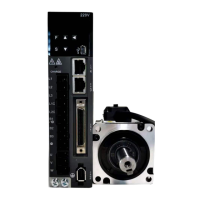
Sequential control input loop
Optocoupler Input Loop
The CN1-IN0 ~ CN1-IN7 terminals of CN1 port will be described below.
Example of relay circuit
Example of open collector Circuit
(Note) The external power supply (DC24 V) must have a capacity above 50 mA.
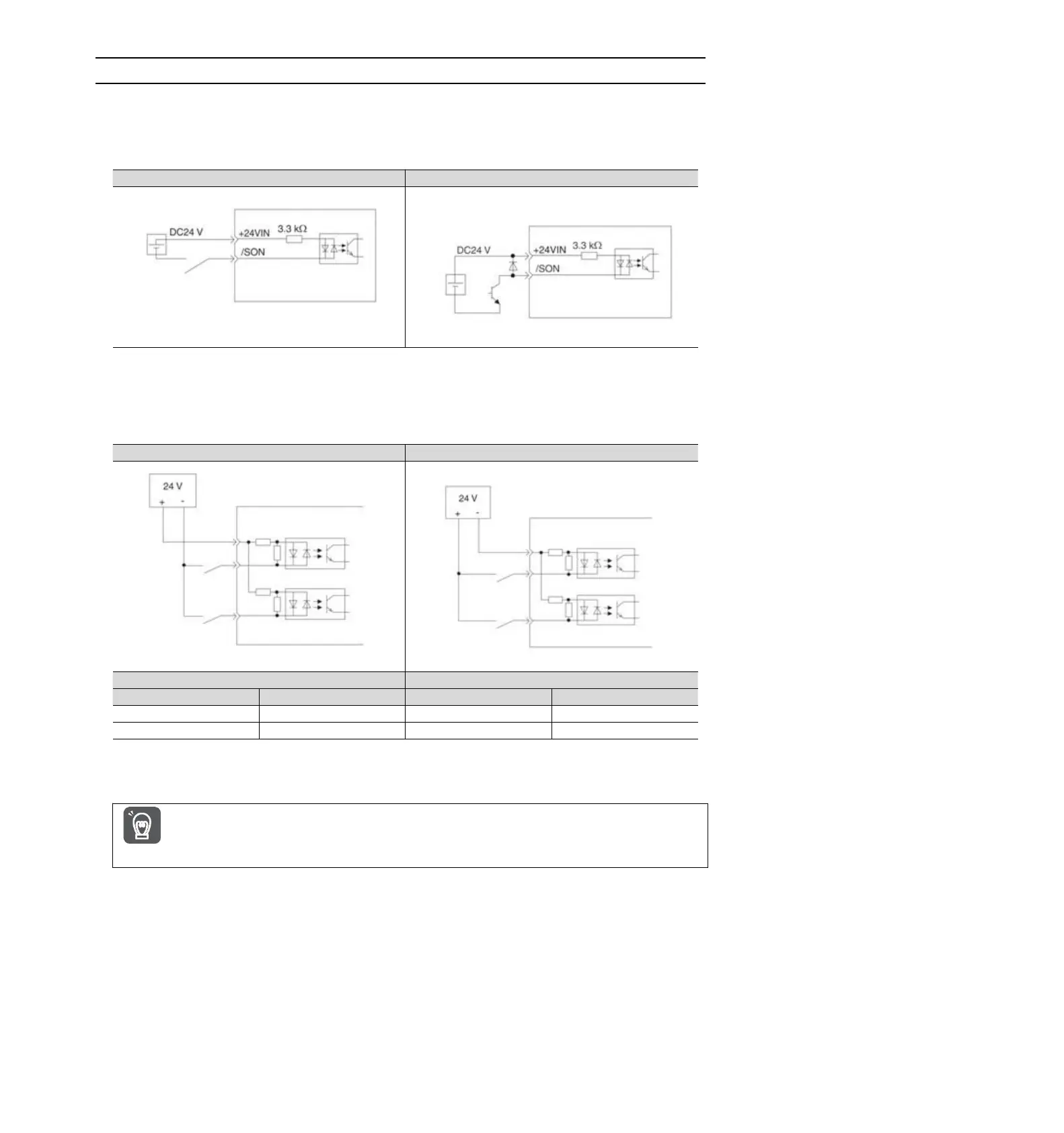
The servo-driven input loop uses a bidirectional optocoupler.
Please select common collector loop connection or common emitter loop connection according to mechanical
specifications.
Common collector loop
Common emitter loop
Polarity of input signal
Photocoupler
Internal level signal
Photocoupler
Internal level signal
ON
L level
ON
L level
OFF
H level
OFF
H level
Sequential control output loop
Important
The output circuit may be short-circuited due to wrong wiring and application of abnormal voltage.
The brake does not operate, which may lead to mechanical damage or casualties when the above-mentioned
faults occur.
Servo unit
Servo unit
etc.
Servo unit input side
Internal
signal
level
Servo unit input side
Switch
Switch
Switch
Switch
Photocoupler
Photocoupler
Photocoupler
Photocoupler
Internal
signal
level
Internal
signal
level
Internal
signal
level

Table of Contents