Electronic gear ratio
B
A
=
Pn20E
Pn210
=
Encoderresolution
Theamountofmovement(commandunit)bywhichtheloadshaftrotatesonecircle
×
m
n
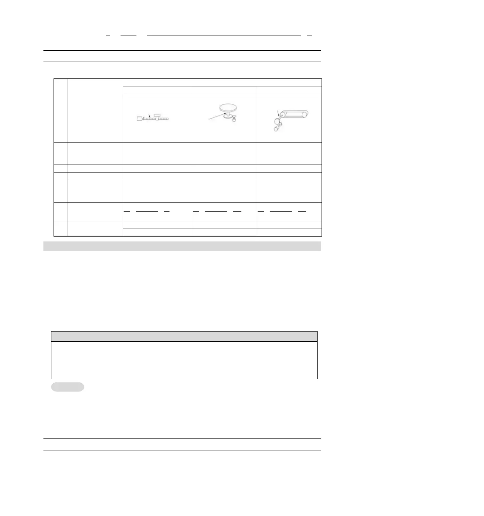
5.12.2 Setting Examples of Electronic Gear Ratio
Examples of settings are as follows.
Lead of ball screw: 6mm
Reduction ratio
1/1
Rotation angle of 1 turn:
360
Reduction ratio 1/100
Pulley diameter :100mm
(pulley circumference:
314mm)
Reduction ratio
1/50
The amount of
movement of the load
shaft by one revolution
(Command unit)
5.13 Setting of Absolute Value Encoder
When the system using absolute value encoder is put into use, the number of revolutions data should be
initialized. Therefore, when initialization needs to be performed such as the first power on, alarms related to
absolute value encoders will occur (A.810, A.820). By setting (initializing) the absolute value encoder, the
alarm related to the absolute value encoder will be cleared after the initialization of the rotation number data is
performed.
In the following situations, please set (initialize) the absolute value encoder.
• When the system is first put into use
• When A.810 (encoder backup alarm) occurs
• When A.820 (encoder and number check alarm) occurs
• When it is necessary to initialize the rotation number data of the absolute encoder
After setting the absolute value encoder, the rotation number data is the value of-2 ~+2 coils. The reference
position of the mechanical system will change, so please locate the reference position of the upper device after
setting.
If the machine is directly operated without positioning the upper device, unexpected actions may occur, resulting
in personal injury or mechanical damage.
1. There is no rotation number data (usually zero) in the following situations, so it is not necessary to set
(initialize) the absolute value encoder.There will be no alarm related to absolute value encoder (A.810,
A.820).
• When using a 1-turn absolute value encoder
• When the multi-turn absolute value encoder is used as one-turn absolute value encoder (Pn002 =
n.2)
2. When using a battery-free absolute value encoder, A.810 (encoder backup alarm) will occur when the
power is turned on for the first time. Perform absolute value after the encoder is set (initialized), A.810 will
not occur.
5.13.1 Precautions in Setting (Initializing)
"A.810 (Encoder Backup Alarm)" and "A.820 (Encoder and Number Verification Alarm)" cannot be released
by the servo-driven alarm reset input (/ALM-RST) signal. Therefore, it is important to set (initialize) the
absolute value encoder.
When an alarm (A.8) monitored by the encoder occurs, please remove the alarm by cutting off the power
supply.