Chapter 6 IO Unit
Beijing HollySys Intelligent Technologies Co., Ltd. All Rights Reserved 113
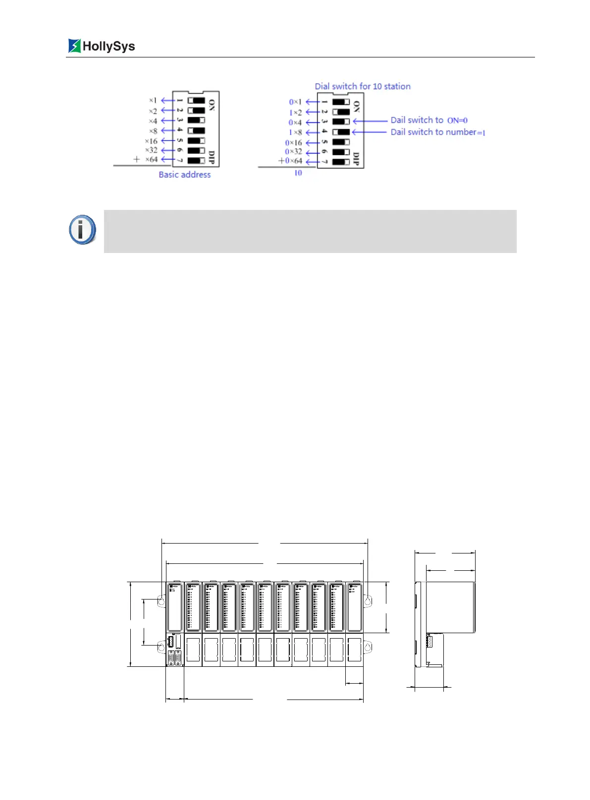
Figure 6-10 Setup of Backboard Base Address
6.2.3 LK117 11-slot Extension Backboard
6.2.3.1 Composition
1 communication slot, 10 I/O slots
Dial code of the base address of the slave station
Redundant PROFIBUS-DP bus interface, DB9 hole receptacle
To support the cascade connection of the extension backboard
24 VDC system power supply interface, 4-pin receptacle
Shrapnel terminals, pluggable
6.2.3.2 Installation Dimension
Apart from power supply, all other LK hardware modules are installed on the backboard. The LK
backboard is surface mounted, fastened to the mounting surface with M4 screws.
All the module widths on the extension backboard are 35 mm. Therefore, for a LK117 backboard, the
horizontal spacing between the crew hole centers on both sides is (35×11+16.5) mm
=
401.5 mm, with
the vertical spacing between the screw hole centers on the same side of 90 mm, as shown in Figure
6-11.
Figure 6-11 Installation Dimension of LK117 Backboard
401.5
385
350=35×10
35
35
90166
100
55.5
95
117.5
In case of multiple backboard cascade connection, it cannot set the
communication addresses repeatedly.

 Loading...