Chapter 7 IO Module
290 Beijing HollySys Intelligent Technologies Co., Ltd. All Rights Reserved
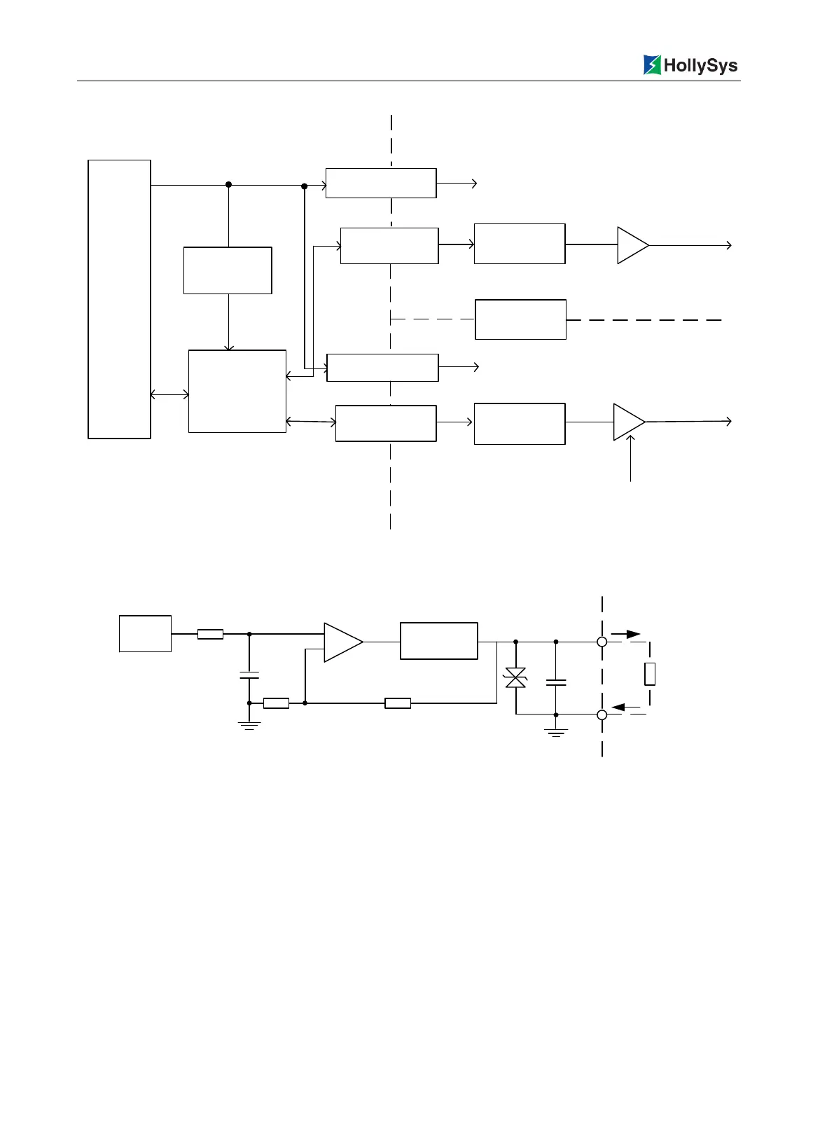
Isolated DC/DC
optoelectronic
isolation
Microprocessor
Backboard
FieldSysterm
See channel interface diagram
Non-isolated
DC/DC
24VDC
Isolated DC/DC
optoelectronic
isolation
D/A
conversion
D/A
conversion
Voltage adjustment
CH1
CH2
A total of four
outputs ,in two case
Channel
isolation
Voltage adjustment
Figure 7-82 Internal Structure Block Diagram
+
-
D/A
Output
protection
Vout
GND
Load
Figure 7-83 LK510 Channel Interface Circuit Diagram
7.9.3 Wirings
The LK510 modules are mounted on the expansion backplane. There are terminal wiring and
prefabricated cable wiring for LK backplane, here only the terminal wiring.

 Loading...