Chapter 7 IO Module
Beijing HollySys Intelligent Technologies Co., Ltd. All Rights Reserved 235
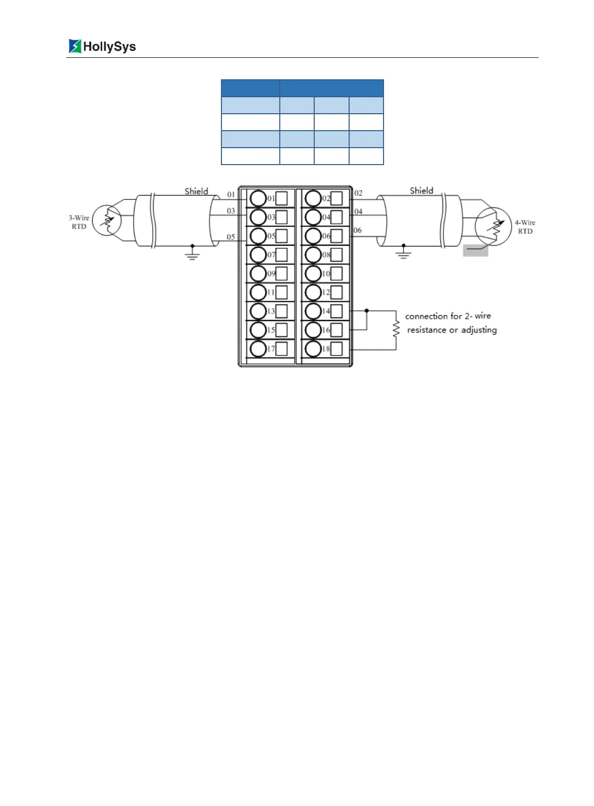
Figure 7-42 LK430 Backboard Terminal Wiring Diagram
Pay attention to the following during wiring:
The two-row 18-channel terminals are fixed on the backboard, located right under the installation
position of the LK430 module.
Each RTD Number in the field is separately connected to the terminals via three conductors
(shielded cable) in the field.
Do not crimp multiple cables on the same terminal. It can realize multipoint connection via a
busbar or a conversion terminal.
7.6.5 Functions
7.6.5.1 Measured Data Output Format
The measured data of each channel of the LK430 module is expressed in a 2-byte positive integer
(decimal: 0~65,535). There are two output formats available for configuration: the output resistance
digital code or the output temperature digital code. See the following for the formula of conversion
between the measured data and the physical quantity:
Output resistance value for configuration selection:
Resistance Value (Ω)=(Resistance Digital Code/65,535)× Full Range Resistance Value +Min.
Measurable Resistance Value in Range, notably, the full range resistance value is equal to the
value obtained by subtracting the Min. measurable resistance with the max. measurable
resistance. For example, in Table 5-31, the max. measurable resistance range for Cu50 is
1~121.75 Ω, then the full range resistance value=121.75-1=120.75.
Output temperature value for configuration selection:
Temperature Value (
℃
/
℉
)=(Temperature Digital Code-10000)/10

 Loading...