Chapter 7 IO Module
Beijing HollySys Intelligent Technologies Co., Ltd. All Rights Reserved 293
For -10.25 ~ +10.25V range, the conversion formula of signal corresponding code value:
Positive voltage range (0 ~ 10.25V): Corresponding code value = Positive voltage signal × 32767
/ 10.25
Negative voltage range (-10.25 ~ 0V): Corresponding code value = 65535 + (negative voltage
signal × 32767 / 10.25)
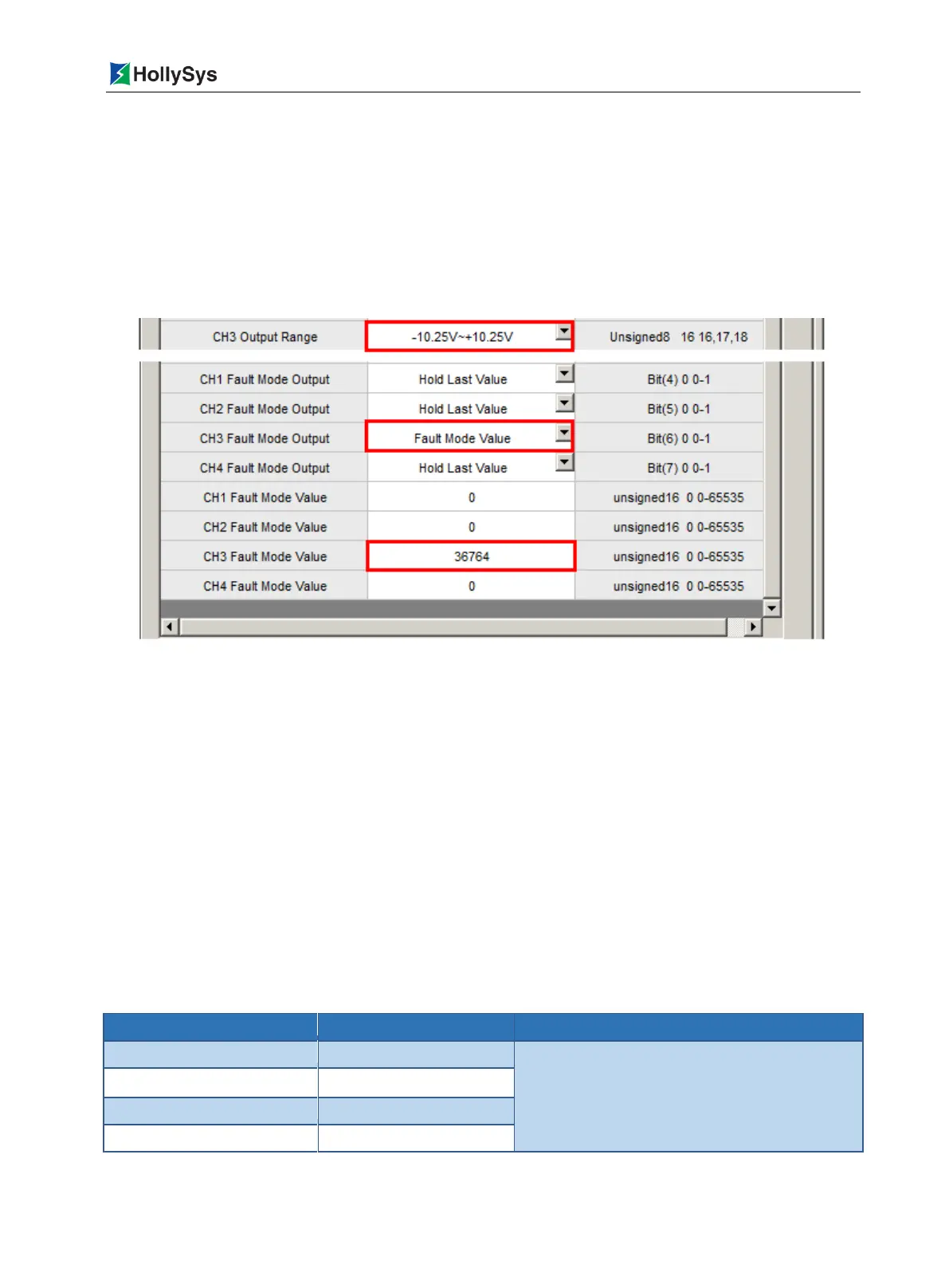
For example, channel 3, if the range "-10.25 ~ +10.25V" is selected and the user-defined fault
mode output is -9V, the output value of fault mode = 65535 + (- 9 × 32767 / 10.25) V = 36764, the
relevant user parameters settings are shown in Figure 7-86.
Figure 7-86 Example of Over-limit Alarm Parameter Setting under Selected Range
7.9.4.2 Over-current protection
The output channel has over-current protection function. When the circuit is shorted, the channel
maximum output current is less than 25mA, which effectively protect the module internal circuit from
being damaged.
7.9.5 Parameter
The user parameter is used to set the operation mode of the module and is written into the controller
when the user program is downloaded. It is not read by each scan cycle. Each parameter has a
default value that can be changed according to the engineering requirements. User parameters do not
support online changes, modification takes effect when it is complete downloaded.
The LK 510 user parameter occupies 21 bytes.
Table 7-71 LK510 User Parameter List
16: -10.25~+10.25V(default)
17: 0~10.25V
18: 0~5.125V

 Loading...