Chapter 7 IO Module
Beijing HollySys Intelligent Technologies Co., Ltd. All Rights Reserved 245
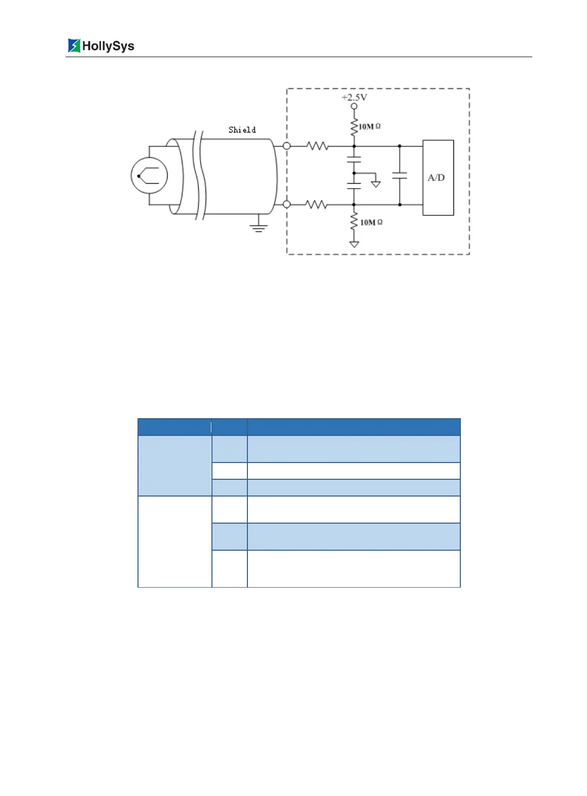
Figure 7-47 LK441 Channel Interface Circuit Diagram
7.7.3 Status Indicator
There are two status lamps on the front panel of the module: the green RUN lamp and the yellow CAL
lamp. The RUN lamp is the run indicator lamp, indicating the communication status between the
module and the CPU module. The CAL lamp is the calibration indicator lamp, indicating the calibration
process.
The LK441 module supports field calibration. The meanings of the indicator lamp are different when in
the running mode and the calibration mode.
Table 7-52 Definition of LK441 Status Indicator
RUN indicator
lamp
(green)
The communication is established, and the module
works well
The communication is not established or incorrect
The module is not powered on
CAL Calibration
Indicator Lamp
(yellow)
In the calibration and detection mode, undergoing
calibration and detection
In the calibration no detection mode, but undergoing
no calibration and detection
It is not powered up or the communication is not
established or the module does not in the calibration
and detection mode
Running Mode
Immediately after being powered on, the module waits for the initialized data, with the green
lamp flashing based on a frequency of 4 times/second.
Upon the completion of initialization, the green lamp is turned normally on, which indicates
that the module works well. In case of any error in the initialized data, communication cannot
be established and the green lamp keeps flashing. Check whether the DP is connected
properly and the communication parameters are set properly.

 Loading...