Chapter 7 IO Module
Beijing HollySys Intelligent Technologies Co., Ltd. All Rights Reserved 291
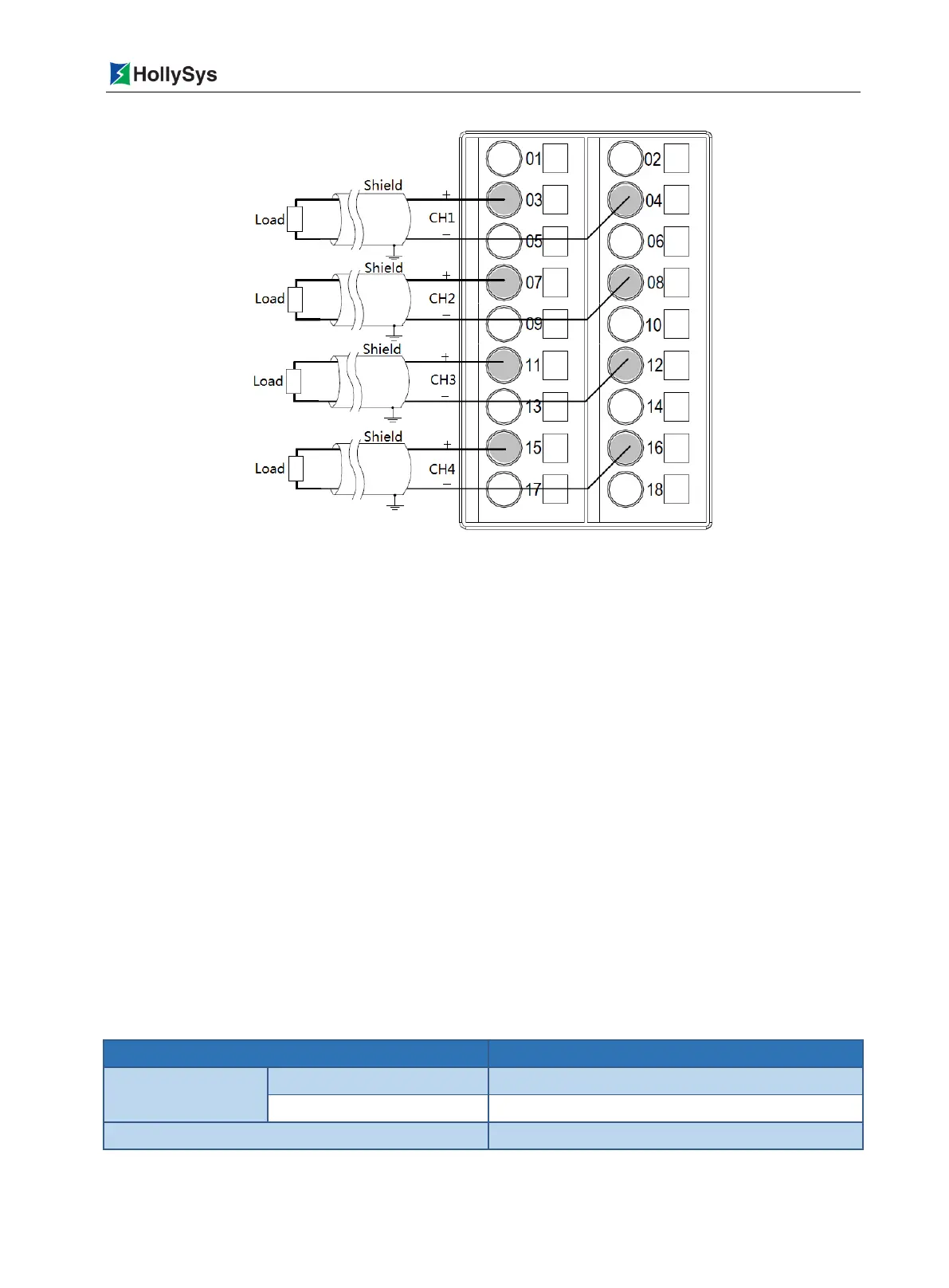
Figure 7-84 LK510 Backplane Terminal Wiring Diagram
LK510 is connected with field signal through the terminal under backplane installation slot. And the
corresponding relationship between the channel and the terminal is shown in Figure 7-84. Wiring, pay
attention to the following:
The AO signal of each way is connected to the terminals with two wires (shielded cable).
Odd terminal is connected to voltage positive terminal, even terminal is connected to voltage
negative terminal.
The terminals that are not connected in the figure are prohibited wiring.
Do not connect multiple cables on the same terminal at the same time. You can achieve
multipoint connection via bus-bar or conversion terminal.
7.9.4 Functions
7.9.4.1 Data format
As shown in Table 7-70, the output data sent to the AO channel of LK510 from controller is
represented by a 2-byte positive integer (decimal 0 to 65535) digital code, where the range (-10.25 to
+ 10.25V) is divided into two sections. The positive voltage (0 ~ 10.25V) corresponds to the decimal
digital code (0 ~ 32767), and the negative voltage (-10.25V ~ 0) corresponds to the decimal digital
code (32768 ~ 65535).
Table 7-70 Corresponding Relationship between Output Voltage and Digital Code

 Loading...