Chapter 7 IO Module
228 Beijing HollySys Intelligent Technologies Co., Ltd. All Rights Reserved
The LK412 module only reports the diagnosis data once separately when an line broken occurs and is
recovered. It can select whether to give an line broken alarm during configuration, defaulted to
disabled. If the input channel is not connected, it can be considered as broken. It is suggested to
disable line broken alarm for channels that are not used, that is, to hold the default parameter
unchanged.
When certain channel is broken, refer to Table 7-41 for the diagnosis and handling of various signal
types. After the line broken is recovered, the channel diagnosis byte reports 0xA0.
Table 7-41 Handling of Broken LK412 of Various Types
The short line (+IN/V) is broken.
The channel diagnosis byte reports line broken fault value 0xA6.
The measured channel data reports 65,535
The field signal line (+IN/I, -IN) is
broken
The channel diagnosis byte reports line broken fault value 0xA6.
The measured channel data reports 0
The field signal line (+IN/V, -IN) is
broken.
The channel diagnosis byte reports line broken fault value 0xA6.
The measured channel data reports 65,535 or 32,767 (with a range
of -10.25~10.25 V)
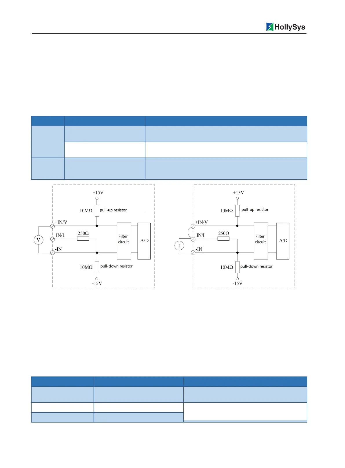
Figure 7-39 LK412 Channel Line Broken Detection Circuit Diagram
7.5.7 Parameters
The user parameter is used to set the operation mode of the module. The CPU module written when
downloading the user program may not be read in each scanning period. Each parameter has a
default, able to modify the parameter value according to the project requirements. The user parameter
does not support online modification. The modification takes effect only upon full download.
The user parameter length of the LK412 module is up to 36 bytes.
Table 7-42 Table of LK412 User Parameters
To select the digital filtering mode
0=50 Hz Filter, to filter 50 Hz interference (default)
1=60 Hz Filter, to filter the 60 Hz interference
To select the range of Channel 1
16= -10.25~10.25 V (default)
17=0~10.25 V
To select the range of Channel 2

 Loading...