Chapter 7 IO Module
204 Beijing HollySys Intelligent Technologies Co., Ltd. All Rights Reserved
to run and the module is undergoing calibration and detection, the yellow is turned on. Upon
the completion of calibration and detection, the yellow lamp then flashes again.
During calibration and detection, the green lamp is normally no. When the communication is
disconnected, the green lamp flashes. When the communication is established again, the
green lamp is turned normally on again.
When the communication is not established or disconnected, the yellow lamp then goes out.
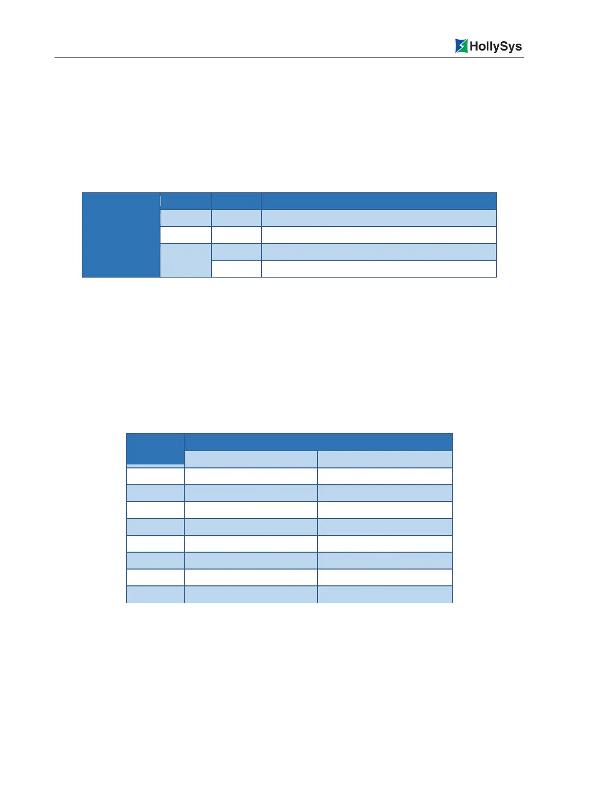
Table 7-21 Definition of LK411 Indicators in Calibration Mode
The communication is not established or incorrect.
Under calibration and detection
Calibration and detection is not conducted or is completed
7.4.4 Wirings
The output channel of LK411 does not supply power externally. When connected to a transmitter
based on the two-wire system, a separate 24 DC field power supply is provided separately externally
to the transmitter. To ensure the isolation between the field and the system, the field power supply
shall be configured separately and cannot be commonly used as the power supply for the backboard.
The LK411 module is installed on the extension backboard. The LK backboard can provide both
terminal connection and precast cable connection. Only the backboard terminal connection is
discussed here.
Table 7-22 Definition of LK411 Backboard Terminals
Positive Terminal of Power input
Negative terminal of Power input

 Loading...