Chapter 7 IO Module
248 Beijing HollySys Intelligent Technologies Co., Ltd. All Rights Reserved
Each thermocouple or millivolt signal is separately connected to the terminals via two conductors
(shielded cable) in the field.
The odd terminal is connected to the positive terminal of thermocouple/millivolt signal. The even
terminal is connected to the negative terminal of thermocouple/millivolt signal.
When adopting set cold junction temperature compensation, Terminals 17 and 18 cannot be
used.
7.7.5 Functions
7.7.5.1 Measured Data Output Format
LK441 can be connected to a thermocouple element of B, E, J, K, R, S, T, N and C type to acquire the
field temperature signal, or it can acquire the millivolt voltage signal within a range of -12~78 mV or
-12~+32 mV.
The measured data on each channel that is reported by LK441, is expressed in form of 2-byte positive
integer (decimal: 0~65,535) digital code. For different ranges, the output format of measured data may
differ. The millivolt range outputs the millivolt digital code corresponding to the field signal.
Thermocouple range outputs the temperature digital code corresponding to the field signal. See the
following for the formula of conversion between the measured data and the physical quantity:
Millivolt range of configuration selection: Millivolt Value mV
=
(Millivolt digital
code/65,535)×Range-12, notably, for -12~78 mV, Range
=
90 mV, for -12~32 mV, Range
=
44 mV.
Thermocouple Range of configuration selection: Temperature Value (
℃
/
℉
)
=
(Temperature
digital code-10000)/10.
For a millivolt range, by calling the function block HEX_ENGIN of the Analog signal Processing
Functions library in the programming software AutoThink, it can convert the 2-byte millivolt code value
into the engineering data. For a thermocouple range, it can obtain the actual temperature value upon
simple operation according to the above formula.
7.7.5.2 Cold-conjunction Compensation
LK441 can adopt the following two methods for cold junction compensation. Both methods require
configuring LK441 with a thermocouple range, with the measured data reported to the CPU module
representing a temperature value (that is, to report the temperature digital code).
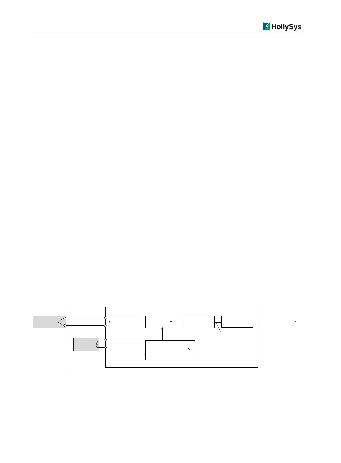
LK411
Channel measuring
millivolt values
+
Millivolt values
mV
=
Millivolt values after
Compensation
Temperature
values after
Compensation
Compensation temperature t
CH1~CH8
compensating
wire
CH9
thermal
resistance
Pt100、Cu50
Field
1.Cold end
temperature measured
2.Setting parameter for
fixed cold end temperature
Thermocouple
Corresponding the table
tempetature-millivolt for
thermocouple
Corresponding the table millivolt-
tempetature for thermocouple
Report temperature code
Figure 7-49 LK441 Cold-conjunction Temperature Compensation Block Diagram
RTD measured cold junction temperature compensation
Each LK441 uses a RTD temperature measurement element to measure the actual temperature
at the cold junction of thermocouple, via the "temperature→millivolt" table corresponding to
thermocouple, automatically verifies the millivolt value corresponding to the cold junction

 Loading...