Chapter 4 System Configuration
Beijing HollySys Intelligent Technologies Co., Ltd. All Rights Reserved 61
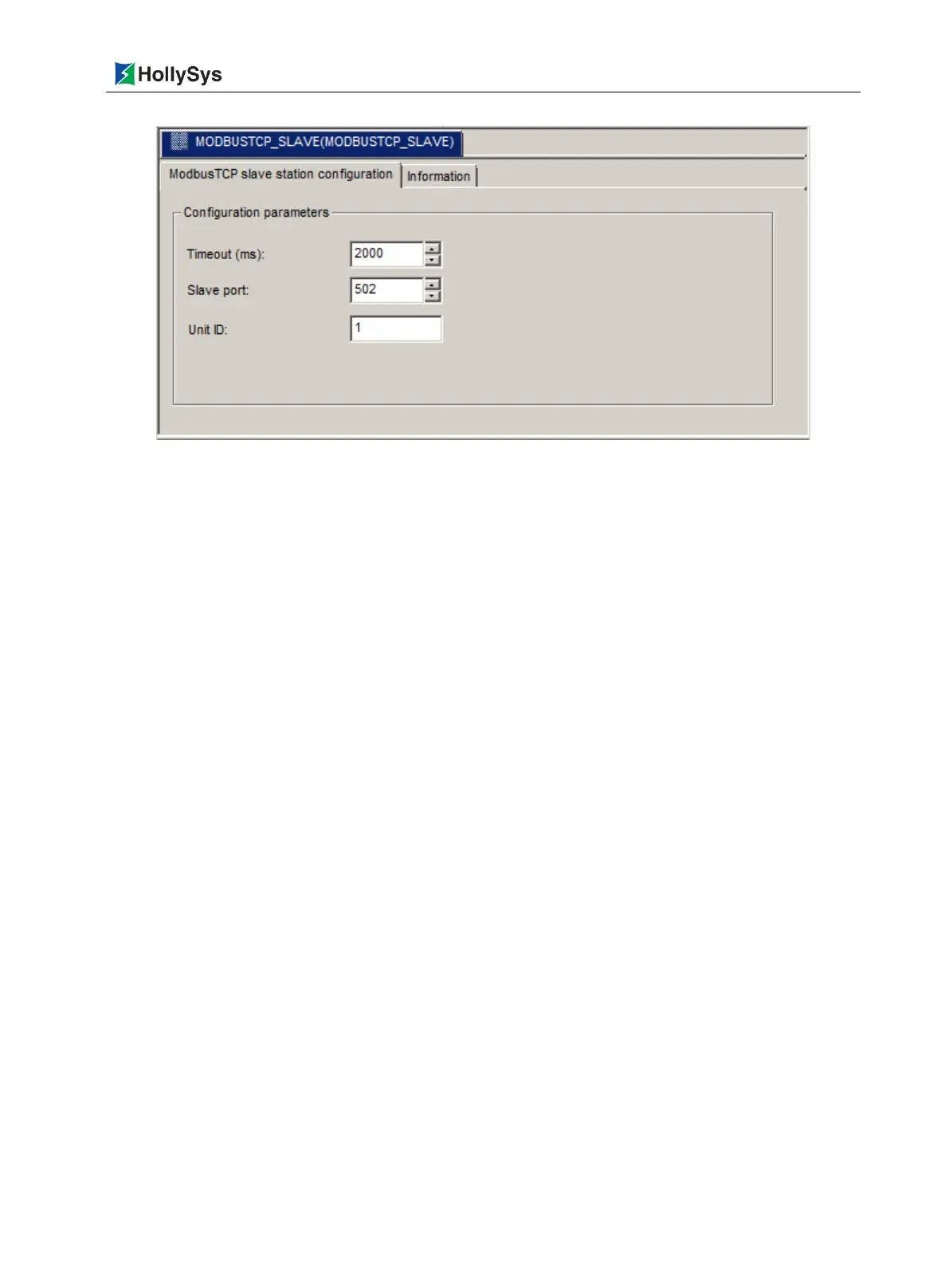
Figure 4-21 MODBUSTCP_SLAVE Configuration Window
Configurable MODBUS TCP slave protocol parameters are displayed in MODBUSTCP_SLAVE
window, and the user can modify the parameter values.
Parameter settings refer to 5.3.10 MODBUS Communication Settings for details.
4.2 System Running
4.2.1 Required Devices
A set of basic hardware for LK series large-scale PLC system: master control backboard, extension
backboard LK117/LK118, power supply module, 24V power switching module LK921, master control
module, communication module, I/O module, connecting cable.
A PC installed with the professional programming software AutoThink and provided with the RJ45
network port.
4.2.2 Device Wiring
Signal wiring of the I/O module.
Wiring of the 24VDC system power supply: positive terminal connected to DC IN
—
1/2+, negative
terminal connected to DC IN
—
1/2
﹣
in LK921 module.
Network wiring: two RJ45 network cable, with one end connected to the network interface of the
PC and the other end connected to the ETHERNET1 or ETHERNET2 port in LK220 module.
PROFIBUS-DP wiring: via the LKA104 to connect the LK249 module in master chassis and slave
chassis, then expand to the backboard LK117/LK118. Also DP can be expanded by LK233.
Redundancy communication wiring: two fiber cable LKA105 are separately connected to the
FIBER X1, FIBER X2 in LK240 module in master-slave frame.
Configure redundancy system, the suggested steps as following:
(1) Network cable, DP cable, fiber cable are connected well (to ensure correct wiring method).

 Loading...