Chapter 7 IO Module
218 Beijing HollySys Intelligent Technologies Co., Ltd. All Rights Reserved
During calibration and detection, the green lamp is normally no. When the communication is
disconnected, the green lamp flashes. When the communication is established again, the
green lamp is turned normally on again.
When the communication is not established or disconnected, the yellow lamp then goes out.
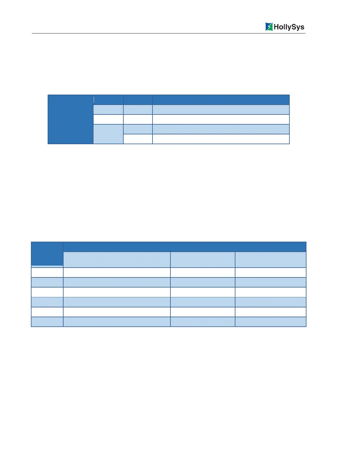
Table 7-32 Definition of LK412 Indicators in Calibration Mode
The communication is not established or incorrect
Under calibration and detection
Calibration and detection is not conducted or is completed
7.5.4 Wirings
The LK412 module is connected with a transmitter based on the two-wire system, and it does not
supply power externally. Each input channel is required to supply a separate external 24 VDC field
power supply to the transmitter. To ensure the isolation between the field and the system, the field
power supply shall be configured separately and cannot be commonly used as the power supply for
the backboard.
The LK412 module be installed on the extension backboard. The LK backboard can provide both
terminal connection and precast cable connection. Only the backboard terminal connection is
discussed here.
Table 7-33 Definition of LK412 Backboard Terminals
Positive Terminal of Voltage Input (+IN/V)
(+IN/V)
Current Input Terminal
(+IN/I)
Common Negative Terminal
(-In)
Pay attention to the following during wiring:
The two-row 18-channel terminals are fixed on the backboard, right located under the installation
position of the LK412 module.
It is non-interfering when selecting each channel range, with an access to both a voltage signal
and a current signal.
For a current signal, Terminals 03 and 01 is short-circuited as the current input terminal of
Channel 1, with Terminals 04 and 02 short-circuited as the current input terminal of Channel 2,
and so on.
Each AI signal is separately connected to the terminals via two conductors (shielded cable) in the
field.

 Loading...