Chapter 3 Installation and Wiring
Beijing HollySys Intelligent Technologies Co., Ltd. All Rights Reserved 31
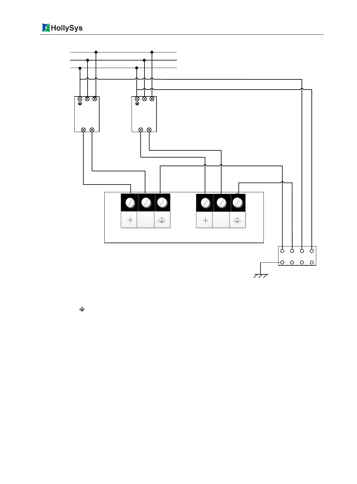
24V+ 24V+
Power
module
V+ V-
DC IN-1 DC IN-2
-
-
Earth
Ground row
N L
Power
module
V+ V-
N
L
24V+ 24V+
LK921
220VAC
L
N
E
Figure 3-14 System Power Wiring
Note: Symbol is functional ground of the system, to discharge electromagnetic interference.
3.2.2 Redundancy Communication Wiring
The LC plug of LKA105 optical fiber is inserted into FIBER X1 ports in the LK240 modules which
located in master/slave frame, respectively. Another group optical fiber is inserted into FIBER X2
ports.

 Loading...