Chapter 7 IO Module
196 Beijing HollySys Intelligent Technologies Co., Ltd. All Rights Reserved
signal is recovered to the normal range and the channel diagnostic byte reports 0xA0.
7.3.6.3 Line Broken Detection
The LK410 module has a line broken detection function.
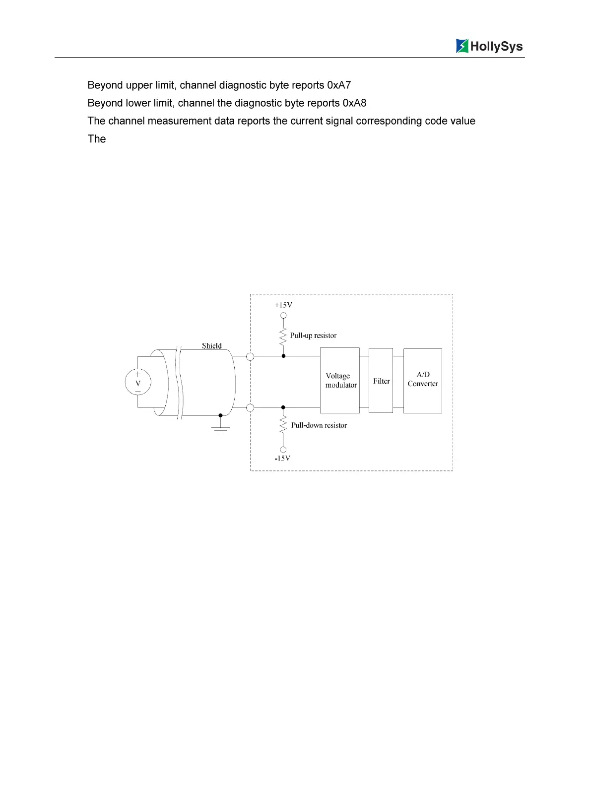
As shown in Figure 7-21, the signal channel is connected with a 10MΩ pull-up resistor. The LK410
conduct the line broken diagnosis by detecting changes of input voltage between the two wiring
terminals. If there is a fault, the fault status is reported to the controller in the form of diagnostic data.
When line broken occurs in the input channel, the positive voltage of the channel is pulled up to + 15V,
the negative end of the channel is pulled down to -15V, the voltage difference at the input end of the
AD converter reaches the maximum value, and the channel diagnostic byte reports line broken; after
line broken recovery, it reports Fault recovery.
Figure 7-21 LK410 Line Broken detection schematic diagram
The LK410 module reports the diagnostic data only once when line broken occurred and line broken
recovery. Whether conduct line broken alarm, configuration optional and the default is disable. If the
input channel is not wired, it is considered as line broken. It is recommended to disable line broken
alarm function for channel not used, that is, the default value of the Line Break Alarm is maintained
and forbidden to modify.
When a channel is broken:
Channel diagnostic byte reports line broken value 0xA6
Channel measurement data reports 65535 or 32768 (-10.25 ~ 10.25V range)
After the line broken is recovered, the channel diagnostic byte reports 0xA0
7.3.7 Parameters
The user parameter is used to set the mode of operation of the module and is written into the
controller when the user program is downloaded. It is not read by each scan cycle. Each parameter
has a default value, which can be changed according to the engineering requirements. User
parameters do not support online modification, modification takes effect only by full download.

 Loading...