Chapter 7 IO Module
Beijing HollySys Intelligent Technologies Co., Ltd. All Rights Reserved 281
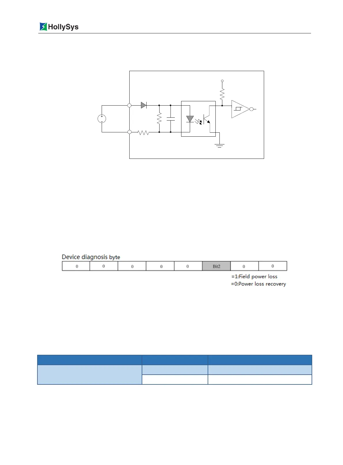
supply voltage is less than 5VDC, the optocoupler switch of the power loss detection channel is OFF,
and it is judged that the field power supply is in power loss status. the field power supply voltage is
between 5 ~ 10VDC, the power failure detection channel of the optocoupler switch status is uncertain.
Figure 7-78 LK620 Field Power Loss Detection Circuit Diagram
When the 24VDC power supply is disconnected (disconnection or power supply output voltage is
less than 5VDC), the device diagnostic data area of the LK620 generates the diagnostic data
"0x04" (Bit2 = 1 in the diagnostic byte). When the next scan cycle arrives, it is reported to the
controller.
When the 24VDC power supply is restored to normal (output voltage 10 ~ 31.2VDC), LK620
device diagnostic area generates a new diagnostic data "0x00" (Bit2 = 0 in the diagnostic byte),
when the next scan cycle arrives, it is reported to the controller.
Only in the event of failure and fault recovery, the diagnostic data of LK620 is reported once
respectively.
Figure 7-79 LK620 Diagnostic Byte
Field power loss detection belongs to device diagnosis, diagnostic byte definition is shown in Figure
7-79. After calling the function block sysGetDPSlaveState (Get Diagnosis of DP Slave), diagnosis
data reported by LK620 are saved into the output parameter
DiagData
in the function block. as shown
in Table 7-65.
Table 7-65 LK620 Diagnostic Information
DiagData [0]:DiagData [1]
Fault recovery or no diagnostic data
7.8.8 Debounce Filtering
The module has a debounce filter function, which can effectively filter out the edge jitter and clutter
interference of the input pulse. It provides multi-file filter frequency of 460kHz, 230kHz, 115kHz, 57kHz

 Loading...