Chapter 7 IO Module
292 Beijing HollySys Intelligent Technologies Co., Ltd. All Rights Reserved
The conversion formula between the output data of the voltage range (-10.25 ~ + 10.25V) and the
physical quantity is as follows:
Positive voltage 0 ~ + 10.25V: Voltage value (V) = Output data /32767 × 10.25
Negative voltage -10.25 ~ 0V: Voltage value (V) = (output data -65535) / 32767 × 10.25
By calling the function block ENGIN_ HEX of the Analog signal Processing Functions library in the
programming software AutoThink, it can convert the engineering data into the 2-byte digital code.
Refer to the HollySys Programmable Logic Controller PLC Instruction Manual for the specific
application of the function blocks.
When setting the fault mode setting value and the programming mode setting value in the user
parameter, the voltage signal needs to be converted into decimal digital code and then fill in. The
digital code conversion method varies from ranges.
For 0 ~ 10.25V, 0 ~ 5.125V range, conversion formula of the signal corresponding code value:
Corresponding code value = voltage signal × 65535 / full scale value
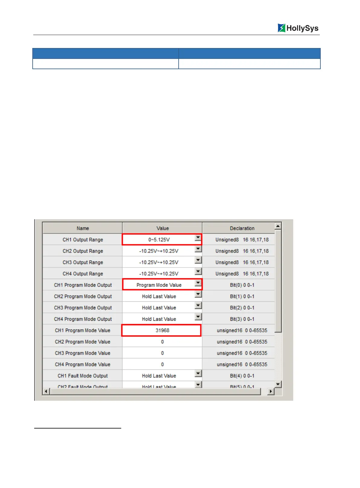
For example, channel 1, if the range "0 ~ 10.25V" is selected and the user-defined programming
mode output is 5V, the full-range voltage is 10.25V, programming mode set value = 5 × 65535 /
10.25 = 31968, the relevant user parameters settings are shown in Figure 7-85.
Figure 7-85 Example of Program Mode Parameter Setting under Selected Range
full scale value equals to the Max. measurable vaule subtracting Min. measurable vaule.

 Loading...