Chapter 7 IO Module
264 Beijing HollySys Intelligent Technologies Co., Ltd. All Rights Reserved
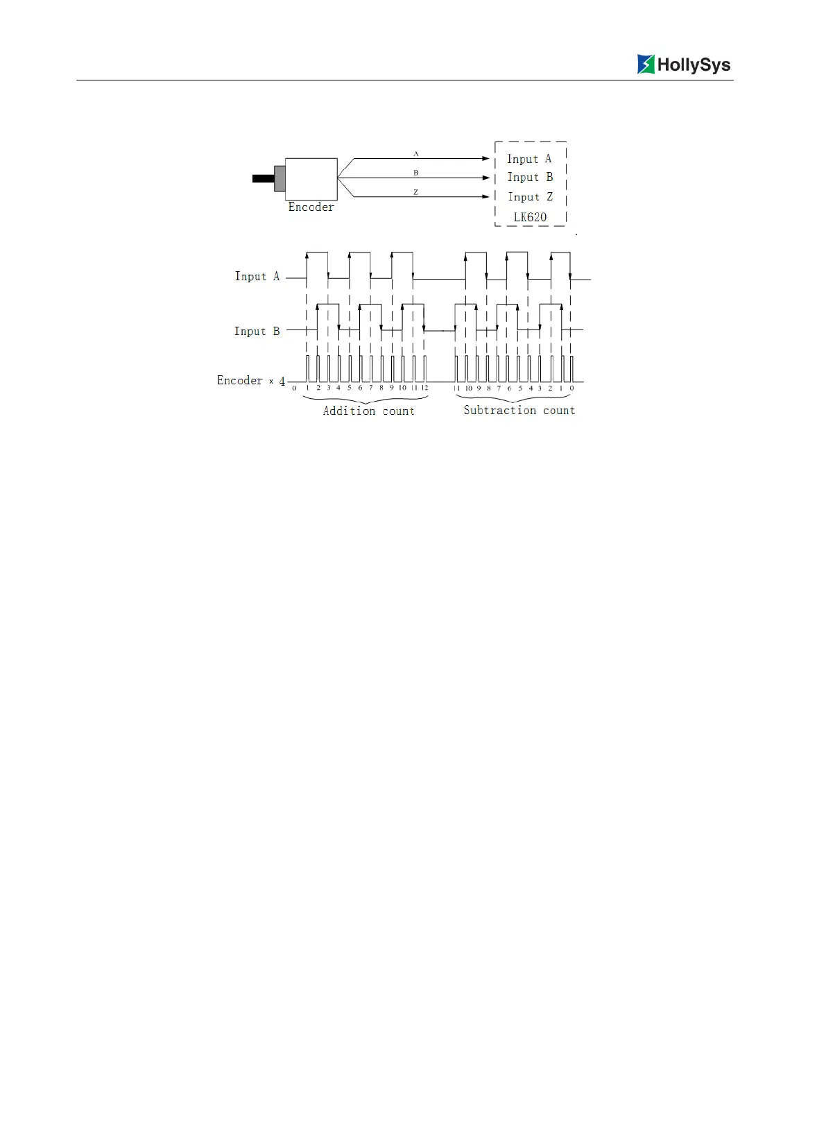
7.8.3.3 Encoder × 4 Mode
Figure 7-57 Encoder × 4 Mode of the Counting Module
In encoder × 4 mode, A-end and B-end input signal maximum allowable frequency are 1MHz with 90°
phase difference. Using the frequency multiplication can achieves double edge the count, and count
when the A-end signal rising edge, falling edge and B-end signal rising edge and the falling edge
arrive.
When the A-end is 90° ahead of the B-end, addition count. When the B-end is 90°ahead of the A-end,
subtraction count.
7.8.3.4 Frequency Measurement Mode
In frequency measurement mode, A-end input frequency signal, B-end and Z-end do not. The counter
records the number of pulses of the A-end frequency signal within a given frequency measurement
period and report to the controller as the current count value. In the configuration, the pulse frequency
is calculated by the frequency count value and the frequency measurement time.
The frequency measurement time is specified by the user. With 10ms as the reference time unit, the
values of the parameters
Counter1_ScalerValue
and
Counter2_ScalerValue
indicate how many
time bases within frequency measurement time. For example, if
Counter1_ScalerValue
is set as 4,
the frequency measurement time of the counter 1 is 4 × 10ms = 40ms. Assuming that the counter 1
receives three pulses in the 40ms frequency measurement time and the pulse frequency = 3 / 40ms =
75Hz obtained from configuration with division operation.
The maximum time for the frequency measurement can be set as 20s. Correspondingly, the maximum
value of the parameters
Counter1_ScalerValue
and
Counter2_ScalerValue
is 2000. The frequency
measurement time should not be set as zero.
In frequency measurement mode, the maximum measurable frequency is 1MHz, the minimum
measurable frequency is 0.1Hz.

 Loading...