Accenta/Optima Engineer’s Manual
11
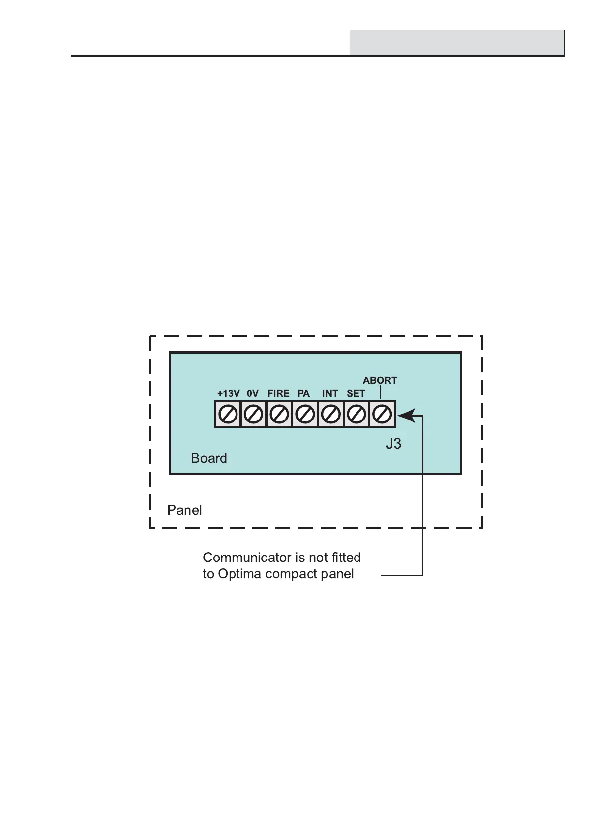
Remote Signalling Input and Outputs
NOTE: These outputs are not applicable to the Optima compact panel.
These terminals have been provided for connection to remote signalling equipment such as a digital communi-
cator, or speech dialler.
13V 0V: These terminals provide a 13V supply for the communicator up to a total load of 200mA.
OUTPUTS (J3): These outputs are programmed as active low output. They are held at 13V and fall to 0V
when active, it can source or sink 10mA.
These outputs would normally be connected directly to the input channels of wire in type communicators.
Alternatively each output can be used to drive a relay (coil resistance > 1200 Ohms ) connected between the
output terminal and the 13V supply terminal. The relay will energise when the output port operates. It is
recommended that a back EMF protection diode is used in parallel with the relay coil.
FIRE: The fire output operates when the fire zone is triggered.
PA: The PA output operates when a PA alarm is triggered or a duress code is used.
INT: The intruder output is operated when an intruder condition is triggered whilst the system is set.
SET: The Set output operates whenever the system becomes set and is used to indicate opening and closing.
ABORT: Operates if the panel is unset within 90 seconds of the alarm condition starting. It is cleared when
the panel is reset by the user or engineer.
Figure 13. Panel communicator
Remote Signalling
ABORT
+13V 0V
FIRE PA INT
SET
 Loading...