EasyManua.ls Logo

Honeywell Accenta Series User Manual

Honeywell Accenta Series
56 pages
To Next Page IconTo Next Page
Page #1 background imageLoading...
Page #1 background image
Engineers Manual
Honeywell Security
Accenta/Optima
0
1
2
3
4
5
6
7
8
9
Set
Reset
PA
Prog
Omit
Chime
Power Day
8EP417A - Accenta LCD keypad
0
1
2 3
4
5
6 7
8 9
CHIME
OMIT
RESET
PROG
SET
1
234
5
6
7
8
ZONE
Accenta +
TA
PA DAY
POWER
PA
8EP416 - Accenta LED keypad
8EP396A Optima compact panel
with built-in LED keypad
Power
A
ccenta
/!
mini
0123
5678
Chime Omit Reset
4
9
Set
Prog
PA
Attack
Tamper
Day
! " # $ % &
Zones

A
ccenta
/!
mini
8SP399A - Accenta mini panel with
remote LCD keypad and communicator outputs.
 
8SP400A - Accenta mini panel with
remote LED keypad and communicator outputs
Gen
"
ACCENTA
8SP419A - Accenta metal panel enclosure with
remote LCD keypad and communicator outputs
OR
8SP420A - Accenta metal panel enclosure with
remote LED keypad and communicator outputs
Question and Answer IconNeed help?

Do you have a question about the Honeywell Accenta Series and is the answer not in the manual?

Honeywell Accenta Series Specifications

General IconGeneral
Zones8
Power Supply230V AC
Battery BackupYes
Tamper ProtectionYes
Communication FormatContact ID, SIA
CommunicationWired
Compatible withHoneywell detectors and accessories
Outputs2

Summary

Introduction

Features

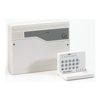
Lists the key capabilities and specifications of the Accenta/Optima system.

Installation

Installation Design

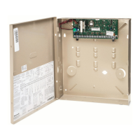
Planning component placement and cable routing for optimal system setup.

Control Panel

Fixing the Control Panel

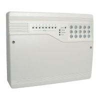
Step-by-step instructions for securely mounting the control panel.

PCB

Wiring the System

Instructions for connecting external circuits to the panel.

Tamper Network

Description of the tamper circuit's purpose and connections.

Connecting Keypads

Connecting Remote Keypads

Guide on wiring up to four remote keypads to the panel.

Remote Keypad

Fitting the Remote Keypad

Detailed steps for mounting the remote keypad assembly.

Security Zones

Recommendations for connecting detectors to system zones.

Zones

Fire Zone

Specifics on programming zones for fire detection functionality.

PA Circuit

Extension Speaker

Instructions for connecting speakers to enhance alarm audio.

Bell Box

External Siren (Bell Box) Output

Wiring instructions for the external siren and tamper circuits.

13V Supply Output

Set

Describes the system's output status when armed.

Remote Signalling

Remote Signalling Input and Outputs

Technical details for communicator connections and data outputs.

Filtering of Intruder alarms

Factory Conditions

Factory Set Condition

Lists the pre-configured parameters upon initial setup.

Defaulting Panel to Factory Settings

Procedure to restore the panel to its original default state.

Defaulting User Code 1 and Engineer Code

Steps to reset user and engineer access codes to defaults.

Mains Connection

Testing the System

Procedures for verifying the correct operation of the installed system.

First Power Up

Engineer Program Mode

Indications on LED Keypads

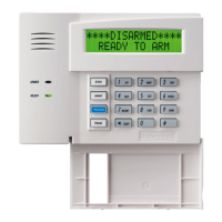
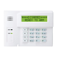
Explanation of the status indicators shown by LED keypads.

System Indications

How the system's status is communicated via its interface.

Entering/Exiting Engineer Program Mode

Menu Options

Alarm Test

Test Outputs

Set Up System Flags

System Flags

Flag 1 - Options

Details the eight specific settings available within System Flag 1.

Flag 2

Flag 2 - Options

Details the specific settings for System Flag 2.

Flag 3

Information regarding System Flag 3, typically software version.

Time & Date

Set Up Time and Date

Procedure for setting the accurate time and date on the system.

Set Up Zone Names

How to assign descriptive names to each security zone.

Timers

Set Up Bell Time

Adjusting the duration for which the external siren (bell) remains active.

Set Up Bell Delay

Set Up Rearm Count

Set Up Codes

Codes (cont'd)

Event Log

View Event Log

Steps to navigate and read recorded system events.

Omit Allow & Double Knock

Double Knock

Configuring the double knock feature to reduce false alarms.

Omit Allow

Omit Allow & Double Knock

Immediate (Intruder) Zone

Entry Time

Setting the duration allowed to enter and disarm the system.

Used Zones

Timed Zones

Setting specific zones to operate with timed entry/exit delays.

Inhibit Zones

Entry Time

Exit Time

Exit Mode

Operating System

Setting the System

Step-by-step instructions for arming the alarm system.

Unsetting the System

Resetting After an Alarm, Tamper or PA

Procedures for clearing system faults and alarms.

Engineer Reset - LCD Keypad

Engineer Reset - LED Keypad

Instructions for performing an engineer reset using the LED keypad.

Faults

Codes

Information on default user and engineer access codes.

Engineer Mode

How to access the system's engineer programming.

Tamper/PA/Fire Faults

How these specific faults impact system operation.

Zone Wiring

Recommendations for optimal detector wiring practices.

Zone Faults

Troubleshooting common issues with zone loop wiring.

Fuses

Procedures and precautions related to system fuses.

Specifications

Appendix 1 - Event Log Messages

Library

Servicing Organisation Details

Parts

A list of available replacement parts for the system.

Engineer Program Mode

Related product manuals