perating and Installation
If you strike a hard surface with a stick it is likely to bounce a few times before coming to re
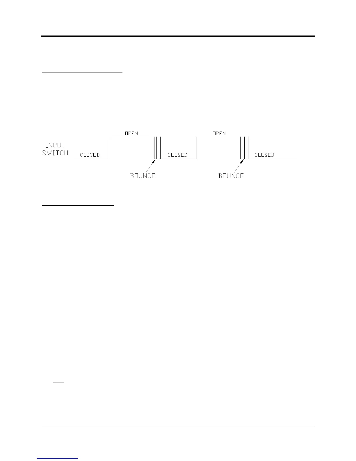
The same is true for most mechanical switches. As the contacts come together they may
“bounce” (open and close a few times), then finally settle in the closed position. This “bouncing”
may be falsely interpreted as several events rather than just on
from this switch it might interpret the bounce as two or three pulses rather than just one.
Electronic switches such as transistors do not have this problem.
The process of “debouncing” requires the switch be in the same state over a specific number of
samples to be considered “valid”.
related. If the input line changes states within t
his period of time the event is ignored and
the debouncing process starts over.
uppose an alarm input is sampled 10 times a second and the
set for 4. This means that the input has to be in the same state
consecutive samples (0.4 seconds) to be considered “valid”. If it changes even once during
this time the entire process starts over. As seen in the illustration the first and second
transitions were ignored because they did not stay in that same
state for 4 samples. However
the third transition was considered to be a “real” event.
will result in the fastest recognition of a change in the
switch. As soon as it changes from one state to another it is considered “v
also lead to inaccurate results if the switch bounces a lot. This setting is normally used with
mechanical switches such as transistors because they do not exhibit bounce problems.
The debounce cycle count can be as high as 255.
The equation is (debounce
seconds. For instance if the sample rate is set to 25 and the debounce is 2, then the input
condition will be recognized in (2
÷ 25) seconds, or 0.08 seconds (80 mS). As an alarm input
this means that the signa
l must be in the active (on) state for at least 80 mS to be considered a
real alarm. As a pulse counting input the signal must be in the active (on) state for at least 80
in the inactive (off) state for another 80 mS to be considered a real pulse.
period of 160 mS translates into a maximum pulse rate of 6.25 pulses per second.

 Loading...


