EasyManuals Logo

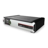
Honeywell CNI2 User Manual

Honeywell CNI2
162 pages
To Next Page IconTo Next Page
To Previous Page IconTo Previous Page
Page #157 background imageLoading...
Page #157 background image
CNI2
O
perating and Installation
Guide
156
ELECTRICAL
DIGITAL OUTPUTS
Number of
outputs
Six outputs are available if not being used as inputs.
Output Configuration
Pus
h
-
pull, +3.3V, 2 mA max.
Programmable as normally
l
ow or normally high.
Source re
sistance
100Ω
Operating Modes
Up to three outputs can be changed remotely using DC
-
2009
®
data collection system.
Any output can be configured to follow an input.
Some outputs can be configured to be used by the CNI2
to control external power sources.
J
7, J9, J1
1, J12 Connector Type
2
-
Pin MTA
with
2.54 mm (0.1”) spacing. Recommended mating connector is AMP 641190
-
2.
TB4 Connector Type
Socket:
RIA Connect Type 343, 4
-
position, Part number
P/N
313431
-
04
Plug
-
in Terminal Block:
RIA Connect
Type 339
, 4
-
position, P
art number
P/N
313391
-
04
Recommended
Output
Cable
Alpha 6300/4, Belden 9534, or equivalent having less than 100pF/ft capacitance. This cable
type is 24awg, shielded, and has a PVC jacket.
Terminate only one end of the cable shield to
signal common or gro
und.
Maximum cable length run should not exceed 1000 feet. Other
cable types or gauges can be also be used as long as careful consideration is given to suitable
wiring practices and performance.
Table of Contents

Questions and Answers:

Question and Answer IconNeed help?

Do you have a question about the Honeywell CNI2 and is the answer not in the manual?

Honeywell CNI2 Specifications

General IconGeneral
BrandHoneywell
ModelCNI2
CategoryRecording Equipment
LanguageEnglish

Related product manuals