EasyManuals Logo

Honeywell CNI2 User Manual

Honeywell CNI2
162 pages
To Next Page IconTo Next Page
To Previous Page IconTo Previous Page
Page #37 background imageLoading...
Page #37 background image
CNI2
O
perating and Installation
Guide
36
TAMPER DETECT & CALL
SWITCH OPTIONS
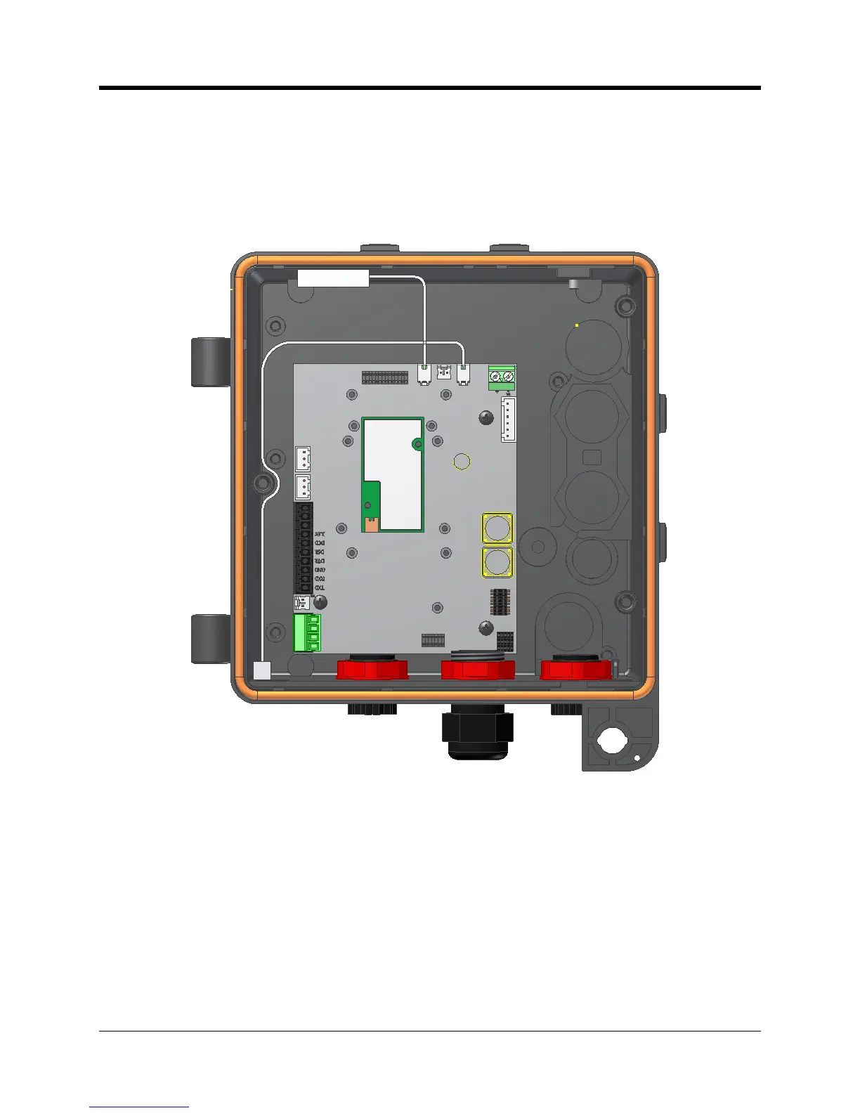
The figure below illustrates where two magnetic det
ect switches have been added to the CNI2.
At the bottom left corner is a seen a small white
magnetic switch
which has been wired into the
J9 connector. This enables a
field t
echnician to swipe
a hand
-
held magnet
wand
(part no. 20
-
7286)
near
bottom left s
ide with in order to initiate a call. In cases where the CNI2 enclosure is
sealed with a lock or wire seal, this form of call trigger is very convenient.
Location of the TAMPER and CALL Switches
The TAMPER switch is seen in the upper left
-
hand corn
er. Not shown is an actuating magnet
attached to the door. When the door is opened the switch activates and can generate an
immediate call into the central office, or the event will be reported on the next scheduled call.

Table of Contents

Questions and Answers:

Question and Answer IconNeed help?

Do you have a question about the Honeywell CNI2 and is the answer not in the manual?

Honeywell CNI2 Specifications

General IconGeneral
BrandHoneywell
ModelCNI2
CategoryRecording Equipment
LanguageEnglish

Related product manuals